
Transmission rate changes in communications networks

a technology of transmission rate and communication network, applied in the field of transmission rate changes in communications network, can solve the problems of increased interference, increased chance of reception errors, and increased interference in the overall network, and achieve significant and sudden increase in the interference of the overall network

Inactive Publication Date: 2008-01-08
FUJITSU LTD
View PDF14 Cites 80 Cited by
  • Summary
  • Abstract
  • Description
  • Claims
  • Application Information

AI Technical Summary

Benefits of technology

[0018]According to a first aspect of the present invention, there is provided a communications network including first and second stations, the said first station comprising a transmitter and the said second station comprising a receiver, the network comprising: transition control means operable, prior to a change in a transmission rate of a preselected signal from said first station to said second station, to cause transitional signals to be transmitted from said first station to said second station over the course of a transitional period expiring before said change is effected, the power levels of said transitional signals being varied over the course of said period in such a way as to reduce a level of instability in the network that would otherwise result from a transmission power change required by said change in transmission rate of that signal.
[0020]According to a third aspect of the present invention, there is provided a base station, for use in a mobile communications network, comprising: transition control means operable, prior to a change in a transmission rate of a preselected signal from the base station to a user equipment of the network, to cause transitional signals to be transmitted from the base station to said user equipment over the course of a transitional period expiring before said change is effected, the power levels of said transitional signals being varied over the course of said period in such a way as to reduce a level of instability in the network that would otherwise result from a transmission power change required by said change in transmission rate of that signal.
[0021]According to a fourth aspect of the present invention, there is provided a user equipment, for use in a mobile communications network, comprising: transition control means operable, prior to a change in a transmission rate of a preselected signal from the user equipment to a receiving station of the network, to cause transitional signals to be transmitted from the user equipment to said receiving station over the course of a transitional period expiring before said change is effected, the power levels of said transitional signals being varied over the course of said period in such a way as to reduce a level of instability in the network that would otherwise result from a transmission power change required by said change in transmission rate of that signal.
[0022]According to a fifth aspect of the present invention, there is provided a communications method for use in a communications network including first and second stations, the said first station comprising a transmitter and the second station comprising a receiver, wherein: prior to a change in a transmission rate of a preselected signal from said first station to said second station, transitional signals are caused to be transmitted from said first station to said second station over the course of a transitional period expiring before said change is effected, the power levels of said transitional signals being varied over the course of said period in such a way as to reduce a level of instability in the network that would otherwise result from a transmission power change required by said change in transmission rate of that signal.

Problems solved by technology

The problem of interference will inevitably increase not only as the number of users increases, but also as the use of high data rate services such as those mentioned above increases.
Generally speaking, the use of a higher transmission rate leads to a greater chance of reception errors since the data bits contained within the signal are more closely spaced and are therefore more susceptible to interference and noise.
As a result of this, when a high data rate service is introduced into the network at the demand of a particular user, the higher transmission power required for this service can lead to a significant and sudden increase in the overall network interference.
This process is usually non-linear and it may take a considerable amount of time for the network to restore balance following the introduction of such a high data rate service transmission.
Unfortunately, these objectives are very difficult to achieve in practice, primarily due to the following reasons.
Firstly, as mentioned above, high data rate transmissions need high transmit powers.
Secondly, the channel conditions at the UE are very difficult for the BTS to estimate accurately in a timely manner.
Therefore, the BTS cannot predict accurately the required power level for a chosen data rate to achieve a certain block error rate (BLER) at the UE.
These problems are exacerbated when a substantial increase in the transmission power is needed, such as when starting a very high data rate (e.g. 2 Mb / s) service.

Method used


Image

  • Transmission rate changes in communications networks
  • Transmission rate changes in communications networks
  • Transmission rate changes in communications networks

Examples


Embodiment Construction

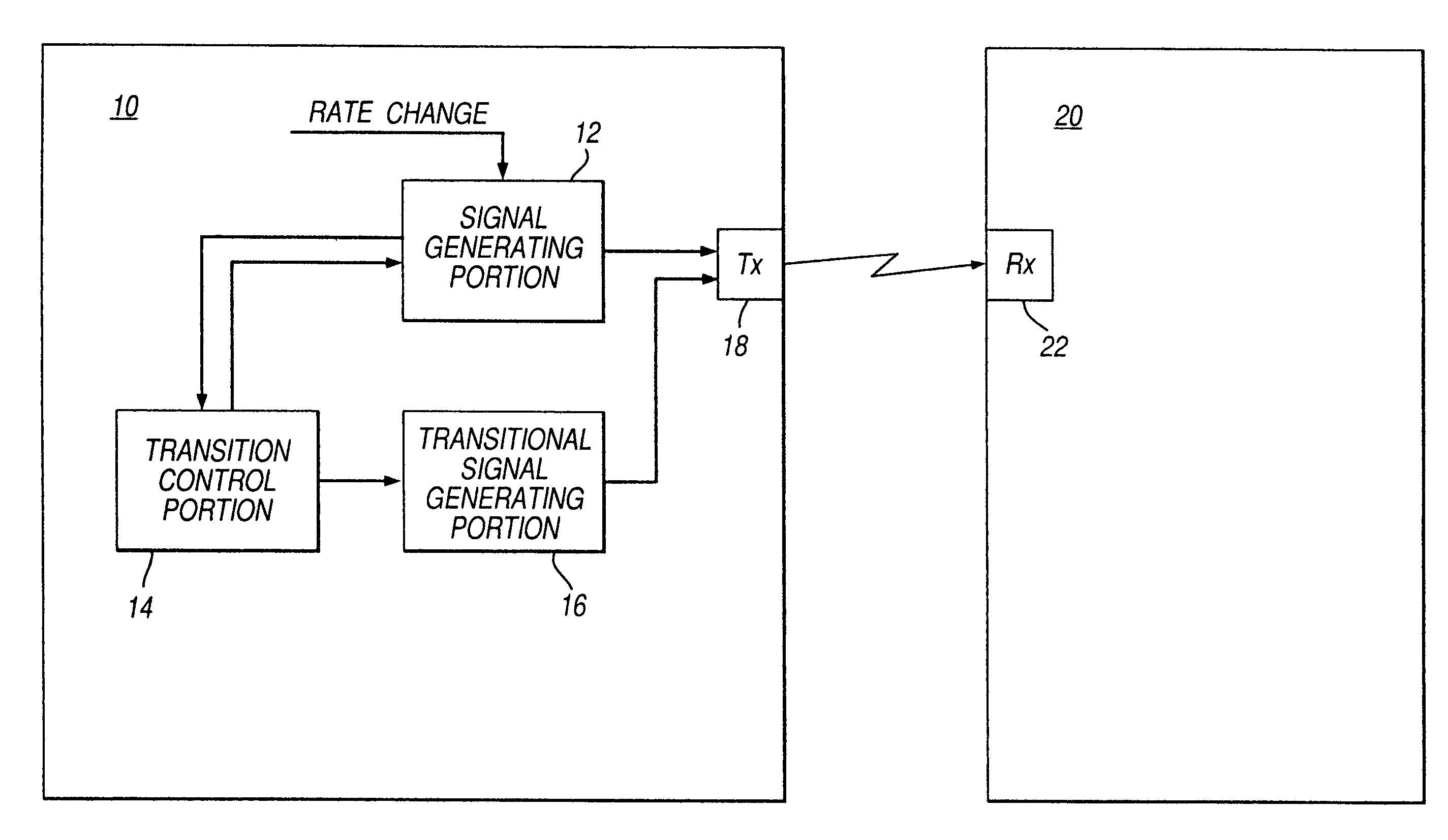
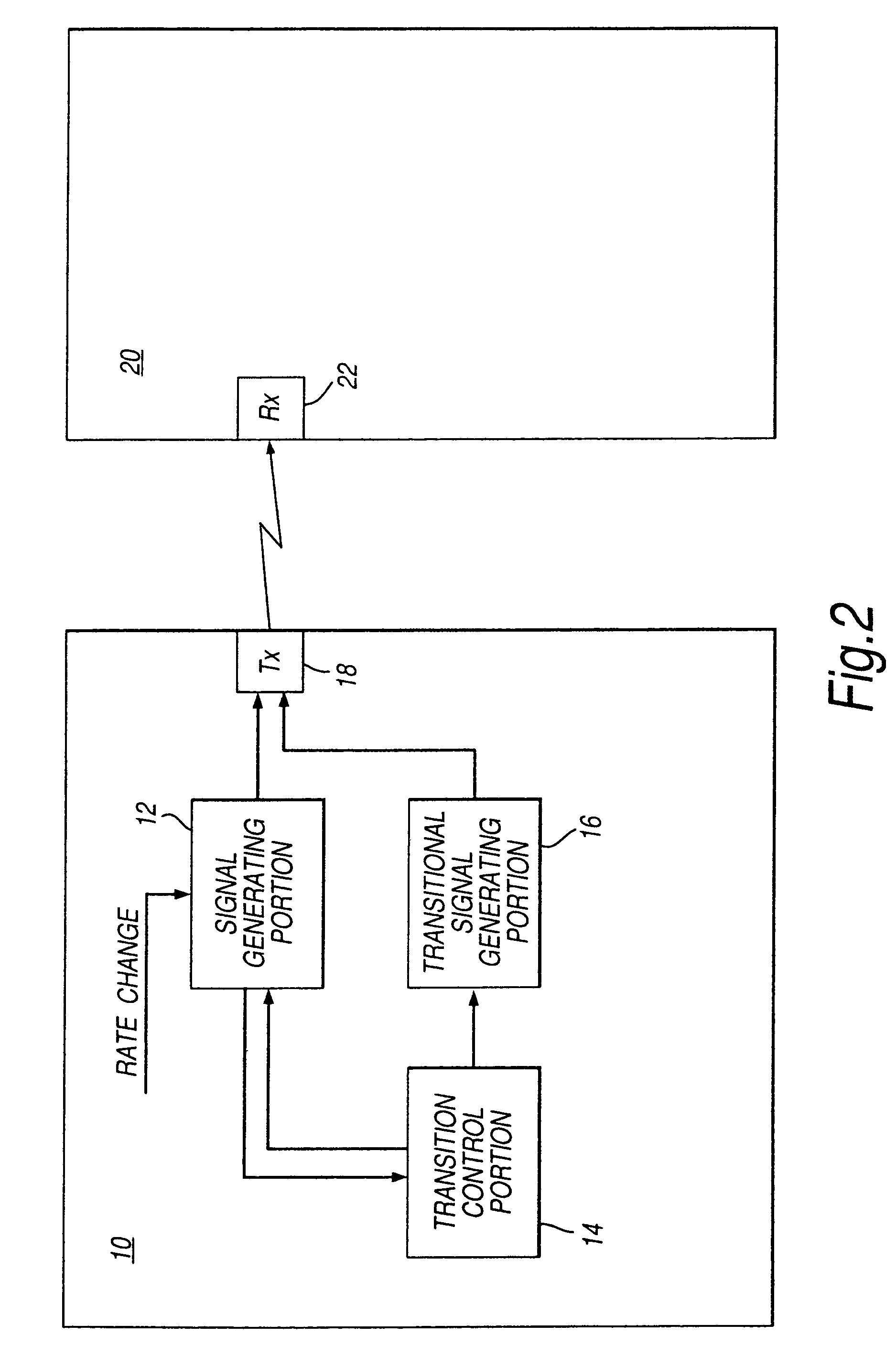
[0048]FIG. 2 is a block diagram showing parts of a mobile communications network embodying the present invention. The mobile communications network includes a base station (BS) 10 in communication with user equipment (UE) 20. The base station 10 comprises a signal generating portion 12, a transition control portion 14, a transitional signal generating portion 16, and a transmitter portion 18. The user equipment 20 includes a receiver portion 22.

[0049]Operation of the base station 10 and the user equipment 20 will now be described with reference to the flowchart shown in FIG. 3. The flowchart of FIG. 3 is just one example of the actions which can be taken when a change is requested in the transmission rate of a particular signal which is being transmitted from the base station 10 to the user equipment 20. The example of FIG. 3 is for the case when a rate increase is required. Prior to such a request for a rate change, which is received in step S1 of FIG. 3, the signal generating port...


PUM


Abstract

A communications network including first and second stations, the first station comprising a transmitter and the second station comprising a receiver. The network further including a transition control portion which is operable, prior to a change in a transmission rate of a preselected signal from the first station to the second station, to cause transitional signals to be transmitted from the first station to the second station over the course of a transitional period expiring before the change is effected. The power levels of the transitional signals are varied over the course of the period in such a way as to reduce a level of instability in the network. In another embodiment probing signals are transmitted prior to making such a rate change to probe a likely relationship between the transmission rate and transmission power after the change is effected.

Description

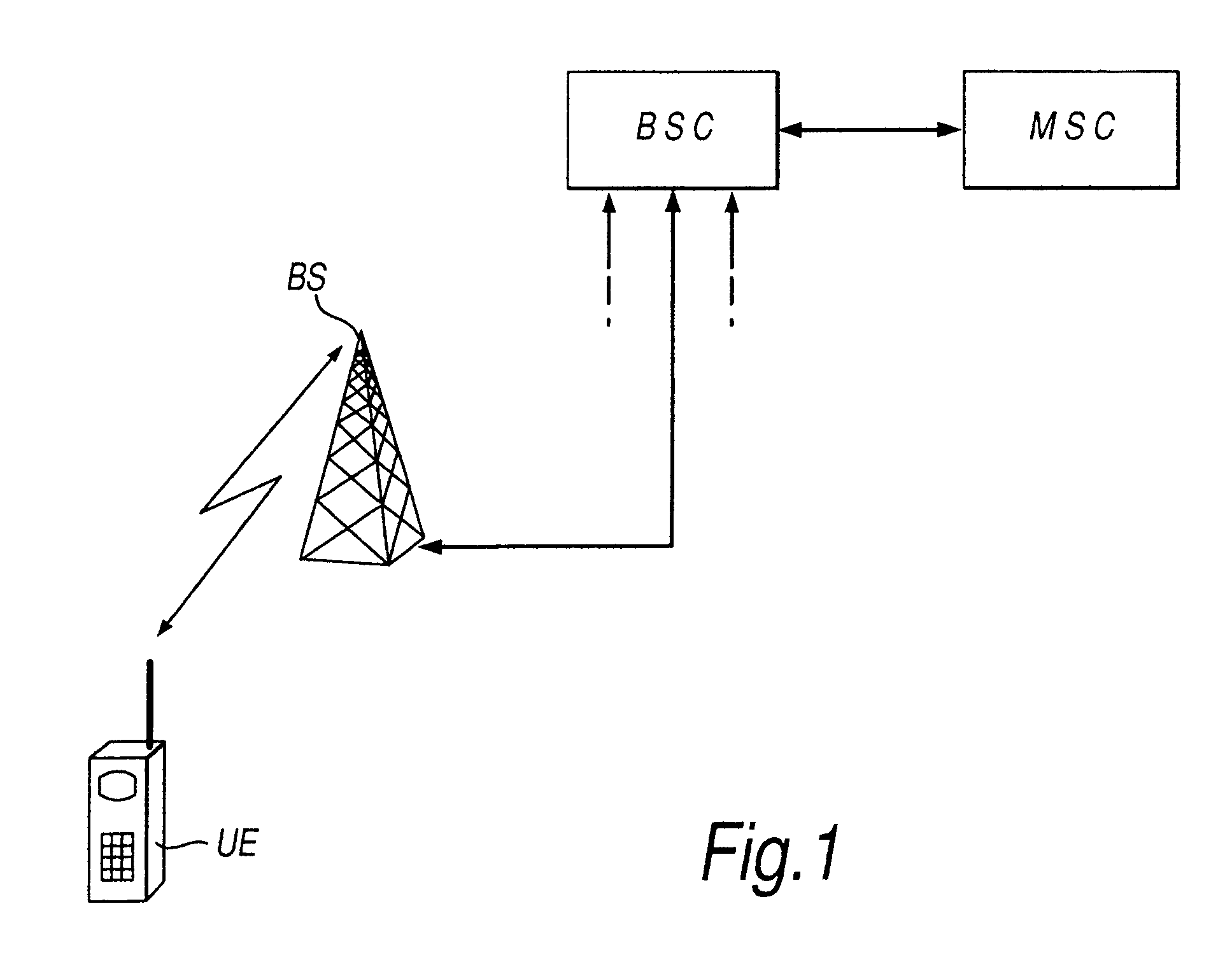
BACKGROUND OF THE INVENTION[0001]1. Field of the Invention[0002]The present invention relates to transmission rate changes in communications networks, for example mobile communications networks such as Wideband Code Division Multiple Access (W-CDMA) cellular networks.[0003]2. Description of the Related Art[0004]FIG. 1 of the accompanying drawings shows parts of a mobile communications network including user equipment UE which is in two-way communication with a base station BS. The base station BS may also be referred to as a node-B. The user equipment UE and base station BS have one or more uplink (or reverse link) channels for transmitting signals (user data and / or control signals) from the user equipment to the base station, and one or more downlink (or forward link) channels for transmitting signals (user data and / or control signals) from the base station to the user equipment. There may be separate data and control channels in one or both directions. In a cellular mobile communi...

Claims


Application Information

Patent Timeline
Patent Type & Authority Patents(United States)
IPC IPC(8): H04M1/00H04B7/26H04B7/005H04W52/22H04W52/26H04W52/36
CPCH04W52/267H04W52/367H04W52/223H04W52/226H04W28/22H04W52/26H04W52/36
Inventor GUO, YINGJIE JAY
Owner FUJITSU LTD
Learn More