
Single patient use vest

a single patient and vest technology, applied in the field of chest compression devices, can solve the problems and achieve the effect of limited durability of the connector

Active Publication Date: 2008-01-08
HILL ROM SERVICES
View PDF86 Cites 34 Cited by
  • Summary
  • Abstract
  • Description
  • Claims
  • Application Information

AI Technical Summary

Benefits of technology

The solution results in a quieter, cost-effective, and easily sterilizable chest compression system that can be packaged and stored efficiently, addressing the limitations of prior art connectors.

Problems solved by technology

The connector is made of a thermoplastic elastomer that provides limited durability to the connector.

Method used


Image

  • Single patient use vest
  • Single patient use vest
  • Single patient use vest

Examples


Embodiment Construction

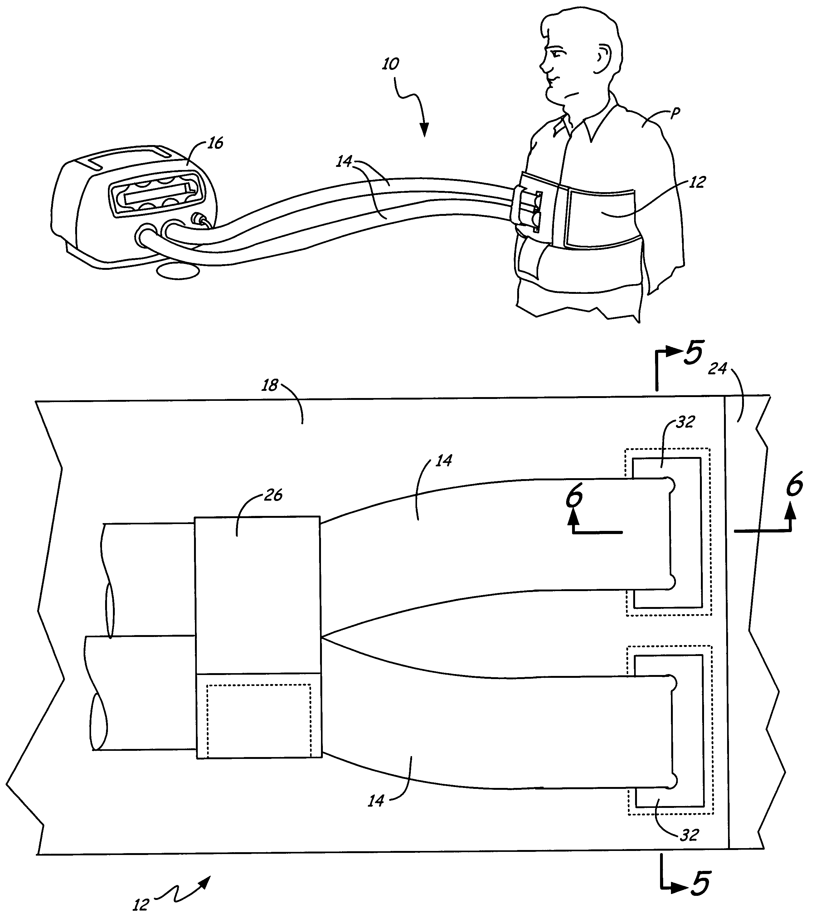
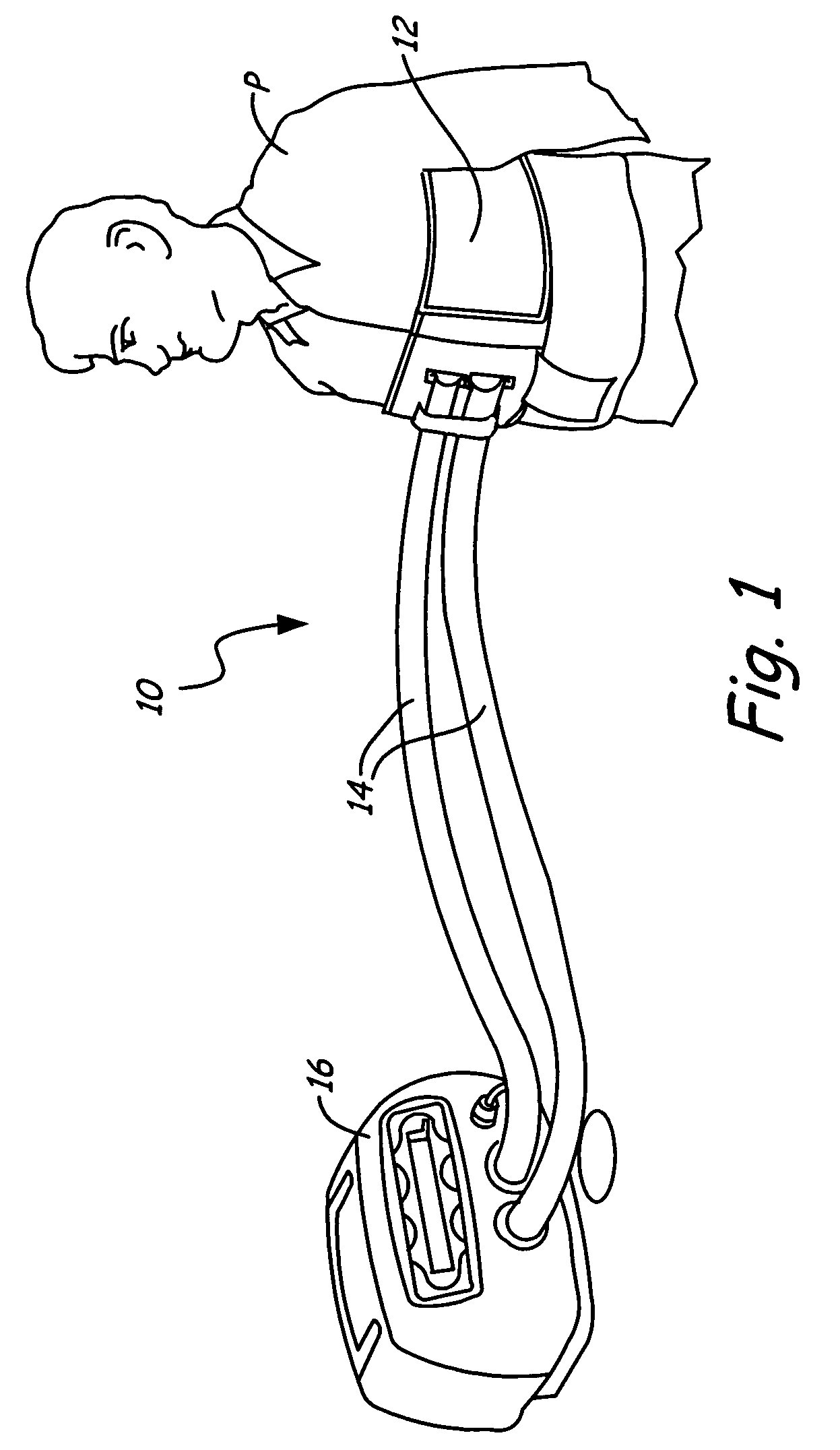
[0016]FIG. 1 shows patient P undergoing HFCWO using a system 10 with a vest 12 of the present invention. System 10 includes vest 12, hoses 14 and air pulse generator 16. Vest 12 fits around the chest of patient P. Hoses 14 connect at one end to vest 12 and at the other end to air pulse generator 16.

[0017]During treatment, air pulse generator 16 generates oscillatory air pulses which travel to vest 12 through hoses 14. The result is oscillatory chest compressions delivered to the chest of patient P for clearing mucus from the lungs of patient P.

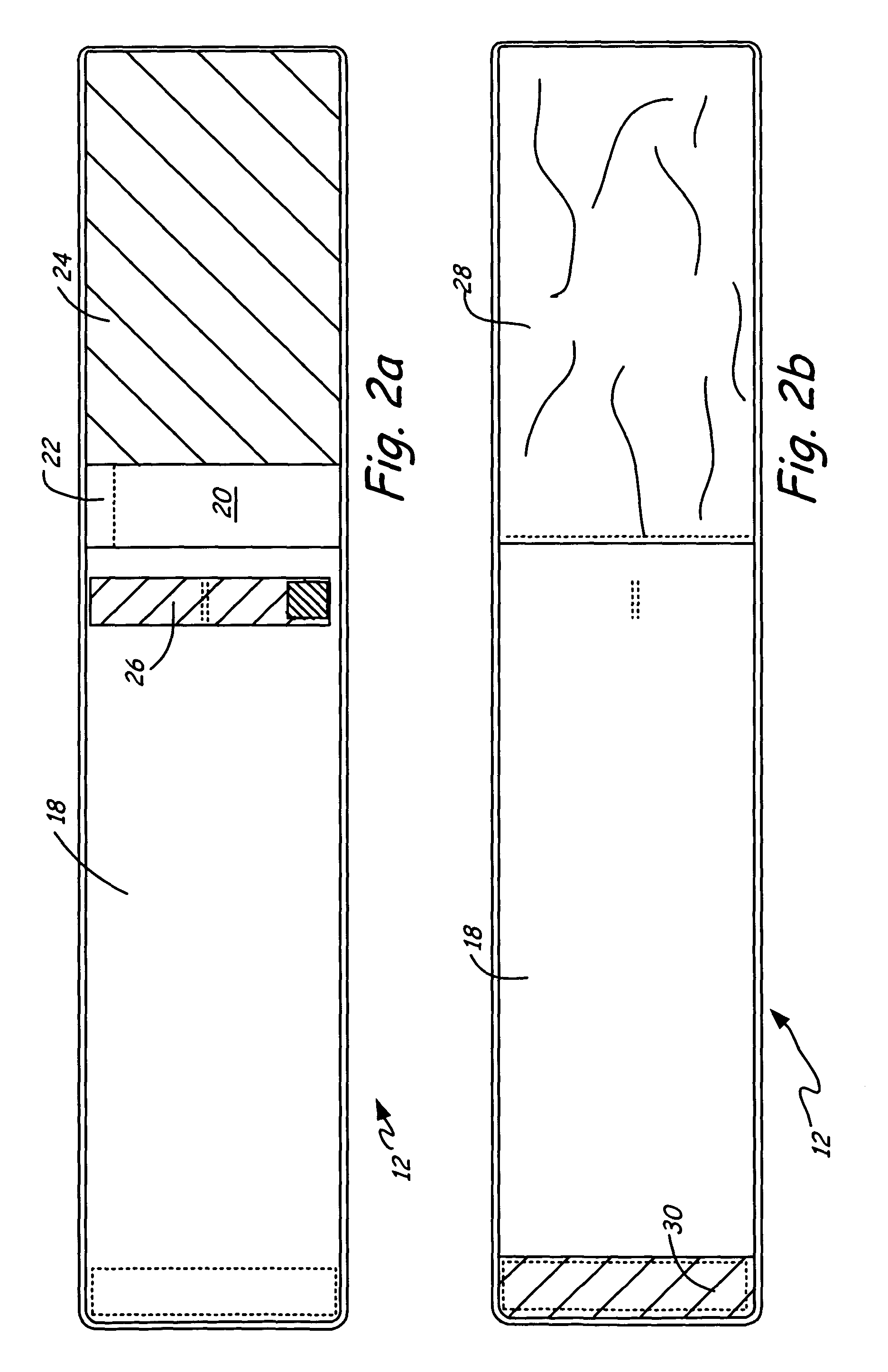
[0018]FIG. 2a shows the outside of vest 12 prior to use. Vest 12 includes belt 18, cover 20 with indicia 22, attachment 24 and hose tie 26. Cover 20 spans across the width of belt 18 and is sewn along the top and bottom edges. Cover 20 covers the area where hoses 14 connect to vest 12, which will later be discussed in detail. Indicia 22, shown as a dashed line on cover 20, indicates that cover 20 should be torn or cut prior to use. Attachment ...


PUM


Abstract

An improved connector having limited durability for a disposable chest compression vest is quiet and cost effective. Among other advantages, the connector is heat sterilizable and flat so that the vest can be efficiently packaged and stacked, which is particularly beneficial for use in a hospital.

Description

BACKGROUND OF THE INVENTION[0001]The present invention relates to chest compression devices and in particular to a high-frequency chest wall oscillator device.[0002]Manual percussion techniques of chest physiotherapy have been used for treatment of a variety of diseases in order to remove the excess mucous that collects in the lungs. A non-exhaustive list of such diseases includes cystic fibrosis, emphysema, asthma and chronic bronchitis, to remove the excess mucous that collects in the lungs. To alleviate dependency on a care giver to provide this therapy, chest compression devices have been developed to produce high frequency chest wall oscillation (HFCWO), the most successful method of airway clearance.[0003]The device most widely used to produce HFCWO is THE VESTairway clearance system by Advanced Respiratory, Inc. (f / k / a American Biosystems, Inc.), the assignee of the present application. A description of the pneumatically driven system is found in the Van Brunt et al. Patent...

Claims


Application Information

Patent Timeline
Patent Type & Authority Patents(United States)
IPC IPC(8): A61H31/00A61H23/04
CPCA61H23/04A61H31/00A61H31/006A61H2201/0103A61H2201/1238A61H2201/165A61H2201/5007A61H2205/08Y10S601/11Y10S601/07
Inventor GAGNE, DONALD J.
Owner HILL ROM SERVICES
Learn More