Illuminated nipple cup

a technology of nipple cup and nipple, which is applied in the field of medical devices, can solve the problems of only finding breast cancer with imaging technique, affecting severely limited therapeutic options and survival rates, so as to improve the aspiration of mammary duct fluid, soften the nipple, and increase blood flow and fluid mobility

Inactive Publication Date: 2008-01-08
LACHOWICZ THEODORE COLLATERAL AGENT
View PDF5 Cites 0 Cited by
  • Summary
  • Abstract
  • Description
  • Claims
  • Application Information

AI Technical Summary

Benefits of technology

[0015]Another port can also be included to permit introduction of a warming liquid prior to activating the vacuum source. For example, warm water can be introduced into the device via the port and subsequently removed from the device via the vacuum port, a separate exhaust port or with a tool such as a pipette or syringe via an access port. A warming liquid serves to soften the nipple and increase blood flow and fluid mobility, thereby enhancing the aspiration of mammary duct fluid.

Problems solved by technology

One problem with mammography is that such an imaging technique can only find breast cancer once it has taken form.
All too often, breast cancer is discovered at a stage that is too far advanced, when therapeutic options and survival rates are severely limited.
A difficulty, however, often arises in identifying the particular mammary duct terminating at a nipple orifice that is yielding the sample fluid because of the relatively small size and natural irregular surface of the nipple.
In practice such an approach, however, typically falls short of generating the desired results.
As such, a physician typically utilizes a head-mounted magnifying glass, thereby making an integrated magnifying lens unnecessary.
Devices, such as that disclosed in aforementioned U.S. Pat. No. 6,328,709, are also problematic for the further reason that nipple heights among patients can vary substantially.
As such the particular focal length of a magnifying lens may not be suitable for the nipples to be examined.
Moreover, by their nature, magnifying lenses cause distortion of the image viewed.

Method used


Image

  • Illuminated nipple cup
  • Illuminated nipple cup
  • Illuminated nipple cup

Examples


Embodiment Construction

[0023]The invention disclosed herein is susceptible of embodiment in many different forms. Shown in the drawings and described hereinbelow in detail are preferred embodiments of the invention. It is to be understood, however, that the present disclosure is an exemplification of the principles of the invention and does not limit the invention to the illustrated embodiments.

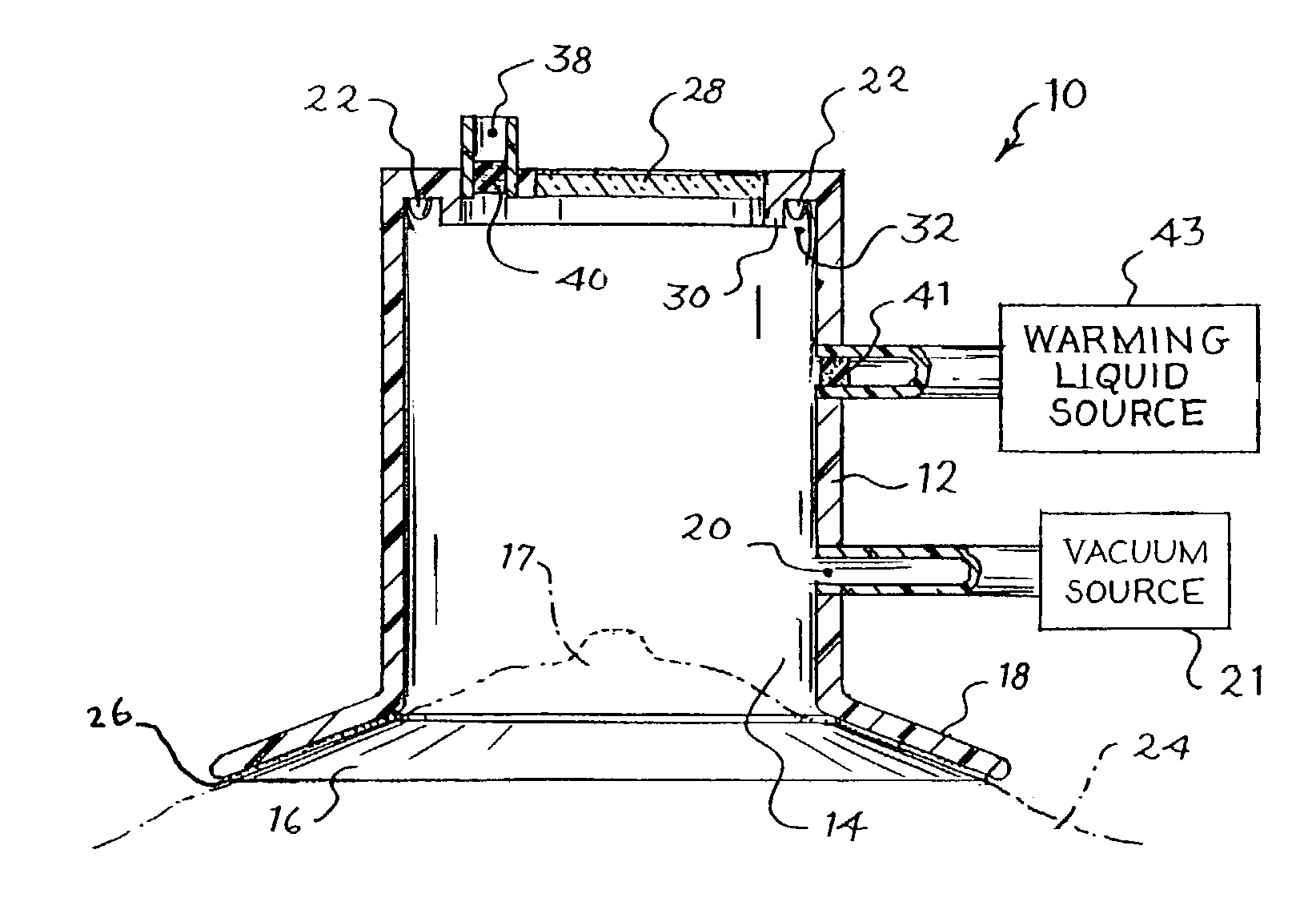
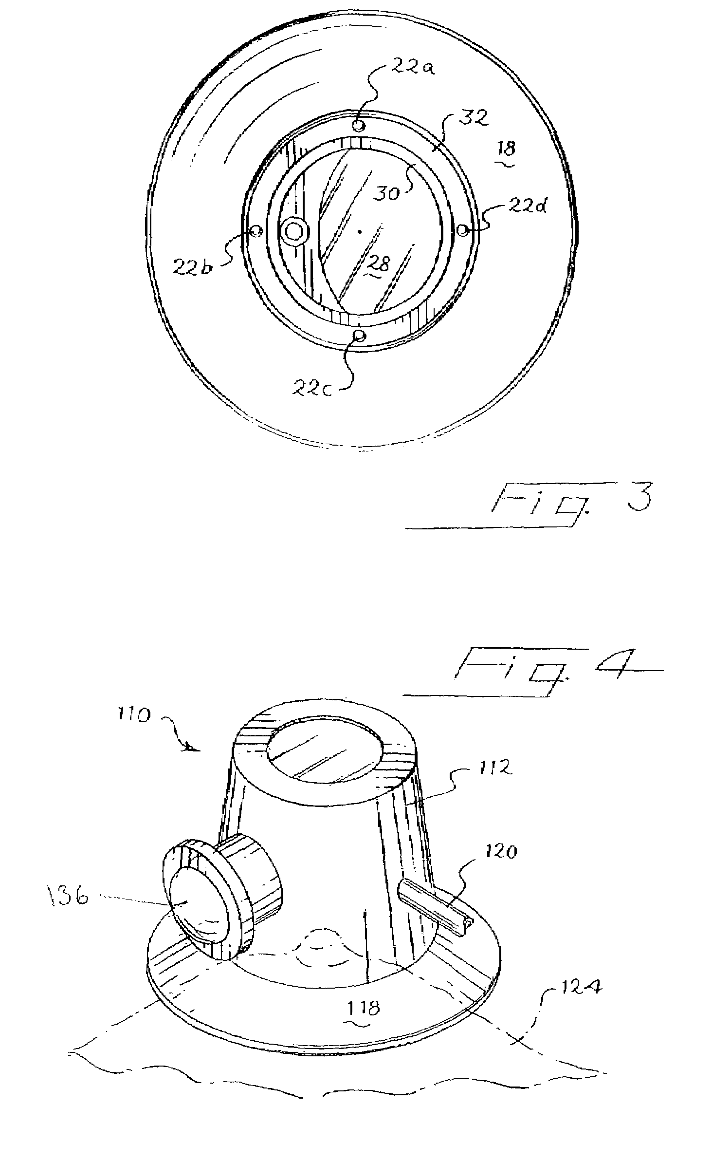
[0024]Referring to FIGS. 1 and 2, device 10 comprises a hollow receptacle 12 defining an interior volume 14, and having an open aperture 16 sized to circumscribe the nipple 17. The open aperture 16 is defined by flange 18, which in turn terminates in rim 19. A vacuum port 20, which is suitable for connection to a vacuum source 21 to create a vacuum in the interior volume 14 is also formed with the hollow receptacle 12. An illumination source 22 to illuminate the nipple 17 within the interior volume 14 is also positioned within the hollow receptacle 12.

[0025]In a preferred form, the flange 18 of the device 10 made o...


PUM


Abstract

A device suitable for viewing and illuminating a mammary duct orifice comprising a hollow receptacle defining an interior volume and an open aperture at a distal end thereof sized to circumscribe the nipple. The open aperture preferably is surrounded by an outwardly extending flange that can be provided with an adhesive. A vacuum port suitable for connection to a vacuum source to create a vacuum in the interior volume may also be configured as part of the hollow receptacle. An illumination source is provided within the device to illuminate nipple orifices when a nipple is positioned within the hollow receptacle.

Description

TECHNICAL FIELD OF THE INVENTION[0001]The invention relates to a medical apparatus for viewing and identifying ductal orifices.BACKGROUND OF THE INVENTION[0002]Breast cancer is one of the health threats most feared by women, and is the most common form of cancer in women. A key to treatment is early detection. For example, an annual mammogram is a method that has been used in hopes of early detection of breast cancer. One problem with mammography is that such an imaging technique can only find breast cancer once it has taken form. All too often, breast cancer is discovered at a stage that is too far advanced, when therapeutic options and survival rates are severely limited. As such, more sensitive and reliable methods and devices are needed to detect cancerous, pre-cancerous, and other cancer indicators of the breast at an early stage. Such methods and devices could significantly improve breast cancer survival. While breast cancer is most common among women, in rare instances the hu...

Claims


Application Information

Patent Timeline
Patent Type & Authority Patents(United States)
IPC IPC(8): A61B10/00A61B5/00A61B17/30A61B19/00
CPCA61B5/0091A61B5/4312A61B10/0041A61B10/0045A61B19/5202A61B2017/308A61B90/30
Inventor MUELLER, JR., RICHARD L.
Owner LACHOWICZ THEODORE COLLATERAL AGENT
Why Eureka
Try Eureka