Eureka AIR delivers breakthrough ideas for toughest innovation challenges, trusted by R&D personnel around the world.

System, method, and apparatus for spilling and filling rotating registers in software-pipelined loops

a software-pipelined loop and rotating register technology, applied in the field of computers, can solve the problems of large loops running out of rotating registers, increasing ii, increasing the compile time of swp, and increasing the complexity of swp implementation

Inactive Publication Date: 2008-01-01
INTEL CORP
View PDF5 Cites 12 Cited by
  • Summary
  • Abstract
  • Description
  • Claims
  • Application Information

AI Technical Summary

Problems solved by technology

However, in spite of these features and the large register sets for integer, floating-point, and predicates available in such processors, there are instances in which large loops may run out of rotating registers.
In such situations, these loops don't get pipelined and the performance suffers.
A possible drawback is that it increases II, compile-time of SWP, and the complexity in implementation of SWP.
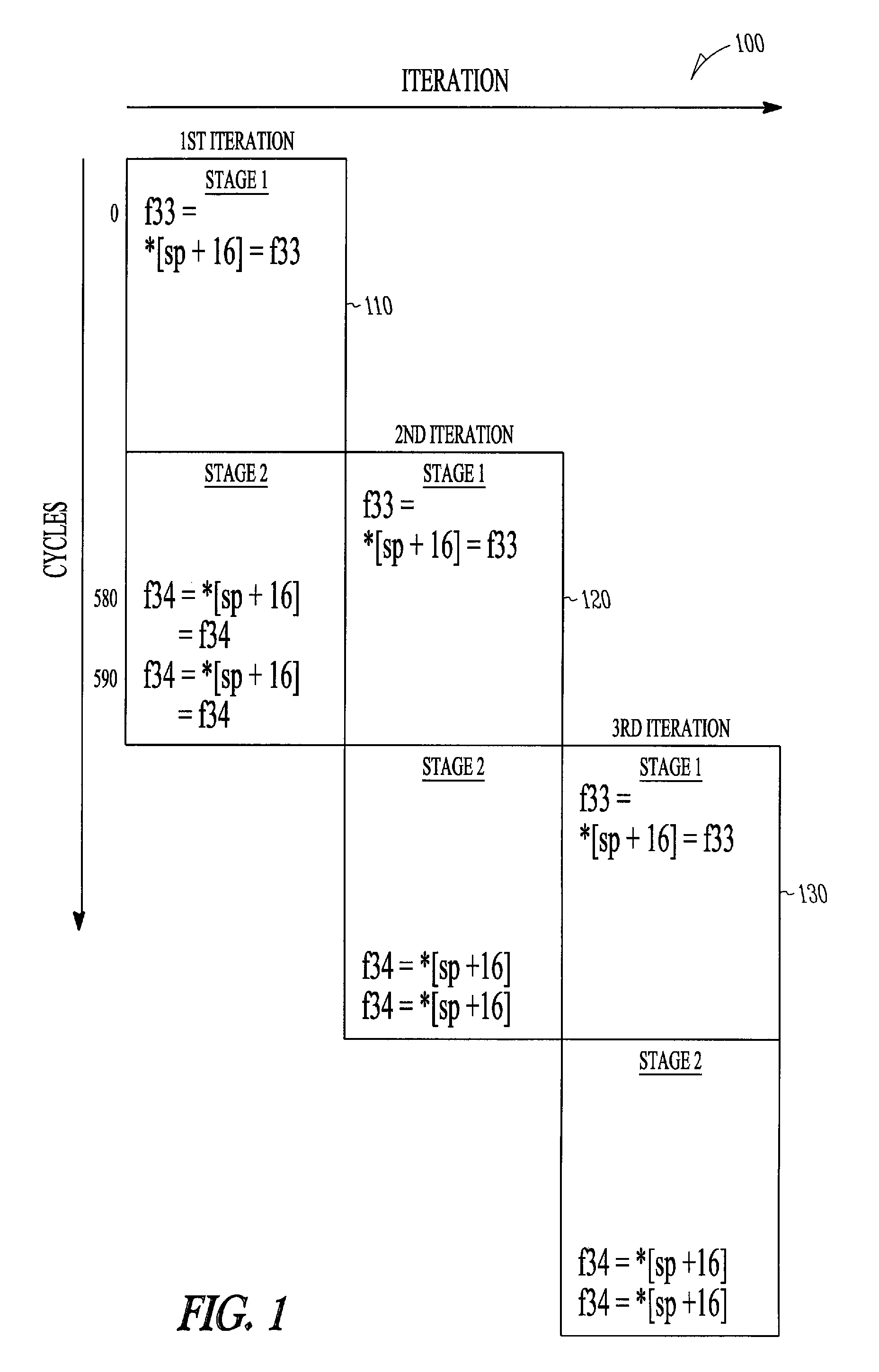
Unfortunately, this approach does not work for spilling and filling of rotating registers because the lifetimes of the rotating registers can be typically greater than II (lifetimes less than II are usually assigned to non-rotating registers).
However, this approach does not work for spilling and filling of rotating registers that hold computed values that are live across multiple stages in a software-pipelined loop.
Therefore, this traditional approach to spilling and filling generally does not work for rotating registers in software-pipelined loops, such as the one illustrated above.
Therefore, the traditional approach to spilling and filling generally does not work for rotating registers in software-pipelined loops, such as the one illustrated above.
In addition, in floating-point intensive loops, there are generally plenty of free integer slots available, and so the spilling and filling using the above technique does not increase II.
However, this may be required where the spilled live range spans more iterations.
The disadvantage is that it may require a higher II for a loop that doesn't have the empty memory slots at the right locations in the pipelined loop.
If empty memory slots are not available at these locations, then this technique cannot be applied without introducing additional bundles, and therefore can increase the scheduled II.

Method used


Image

  • System, method, and apparatus for spilling and filling rotating registers in software-pipelined loops
  • System, method, and apparatus for spilling and filling rotating registers in software-pipelined loops
  • System, method, and apparatus for spilling and filling rotating registers in software-pipelined loops

Examples


Embodiment Construction

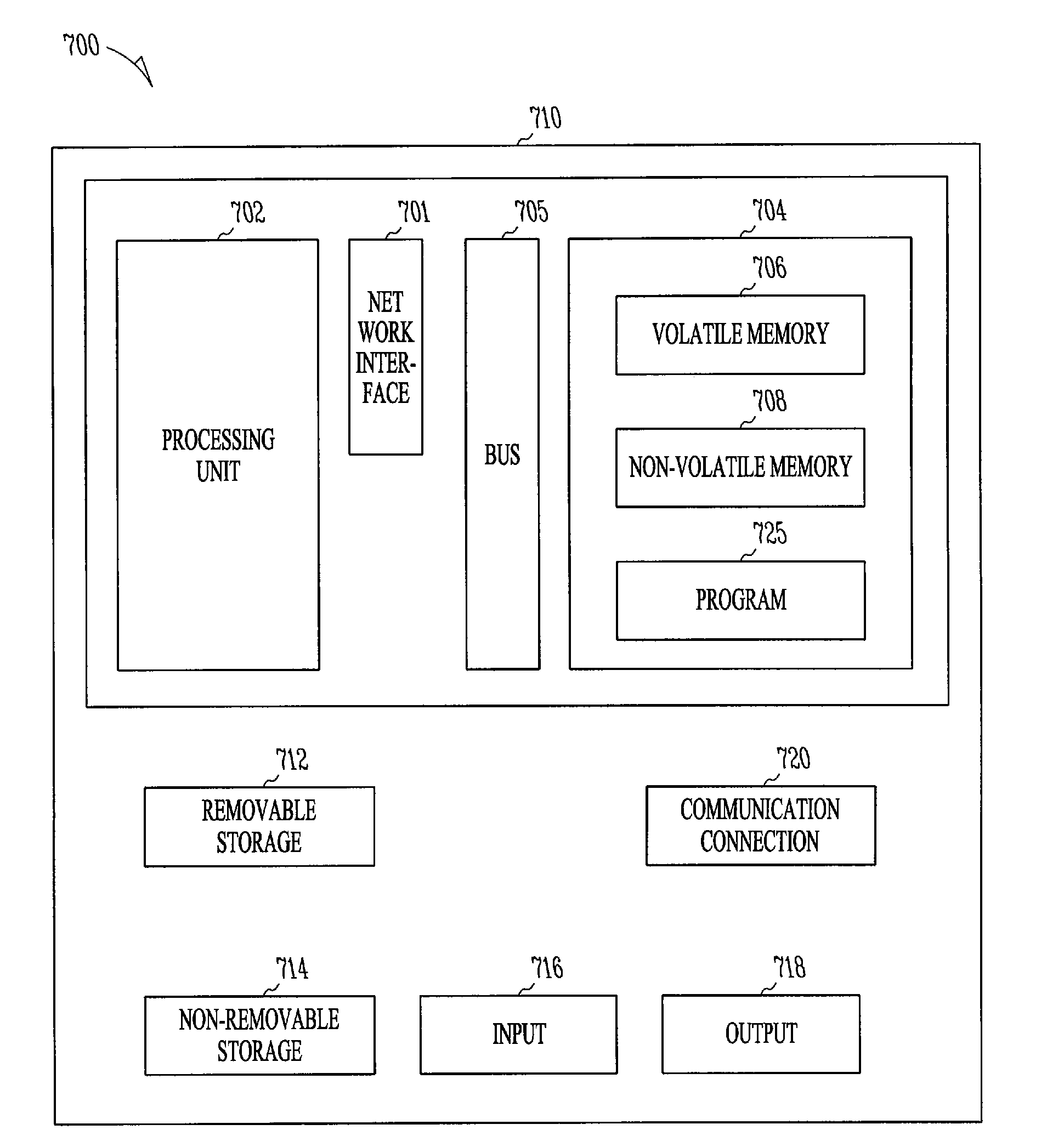
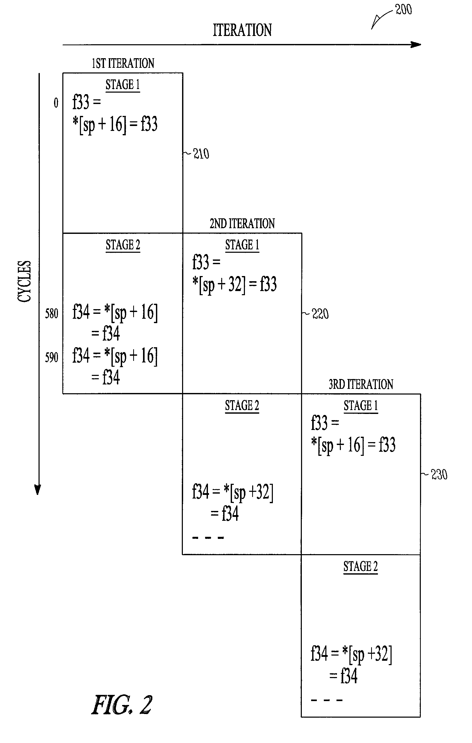
[0014]The present subject matter provides novel apparatus, methods, and computer programs for spilling and filling of rotating registers in software-pipelined loops to reduce Initiation Interval (II), compile-time of software-pipelining (SWP), and / or complexity of implementation of SWP.

[0015]In the following detailed description of the embodiments of the subject matter, reference is made to the accompanying drawings that form a part hereof, and in which is shown, by way of illustration, specific embodiments in which the subject matter may be practiced. These embodiments are described in sufficient detail to enable those skilled in the art to practice the subject matter, and it is to be understood that other embodiments may be utilized, and that changes may be made without departing from the scope of the present subject matter. The following detailed description is, therefore, not to be taken in a limiting sense, and the scope of the present subject matter is defined only by the appe...


PUM


Abstract

An efficient method for software-pipelining (SWP) of loops to translate programs, from higher level languages into equivalent object or machine language code for execution on a computer. In one example embodiment, this is accomplished by spilling and filling multiple computed values, in a register, that are live across multiple stages in a software-pipelined loop, using multiple rotating stack memory locations to reduce compiler-time of SWP, and complexity of the implemented SWP.

Description

TECHNICAL FIELD OF THE INVENTION[0001]The present subject matter relates generally to compilers for computers and more particularly to software-pipelined loops.BACKGROUND[0002]Optimizing compilers are software systems for translation of programs from higher level languages into equivalent object or machine language code for execution on a computer. Optimization generally requires finding computationally efficient translations that reduce program runtime. Such optimizations may include improved loop handling, dead code elimination, software-pipelining, better register allocation, instruction prefetching, and / or reduction in communication cost associated with bringing data to the processor from memory.[0003]Certain programs would be more useful if appropriate compiler optimizations are performed to decrease program runtime. A number of compilation techniques have been developed to improve the efficiency of loop computations by increasing instruction-level parallelism (ILP). One such m...

Claims


Application Information

Patent Timeline
Patent Type & Authority Patents(United States)
IPC IPC(8): G06F9/44G06F9/30G06F9/45G06F15/00
CPCG06F8/4452G06F9/3013G06F9/30134
Inventor MUTHUKUMAR, KALYAN
Owner INTEL CORP
Why Eureka
Eureka Blog
Learn More