Disk driving apparatus and information readout method with selective servo control for read-out destinations of lands and grooves

a technology of information readout and drive apparatus, which is applied in the direction of data recording, instruments, disposition/mounting of heads, etc., can solve the problems of inability to obtain optimum rf signals from the land and the groove, inability to directly apply the conventional control method of completing the track by one period of tracking error signal, and inability to obtain optimum rf signals. , to achieve the effect of improving the accuracy and reliability of information reproduction

Inactive Publication Date: 2008-01-01
SONY CORP
View PDF18 Cites 8 Cited by
  • Summary
  • Abstract
  • Description
  • Claims
  • Application Information

AI Technical Summary

Benefits of technology

[0014]The main advantage of the present invention is that the scanning by the readout means may be accurately controlled by the readout means to improve the accuracy and reliability of information reproduction.
is that the scanning by the readout means may be accurately controlled by the readout means to improve the accuracy and reliability of information reproduction.

Problems solved by technology

However, when reading out the information from an optical disc, including lands and grooves, such as DVD-RAM, the tracking error signals are inverted in polarity from the case where the read-out destination is a land to the case where the read-out destination is a groove, and vice versa, so that the tracking error signals cannot directly be used for tracking control.
However, in such case, it is necessary to complete the half-track jump operation within one half period of the tracking error signal obtained during the track jump operation, such that there is raised a problem that a conventional control method of completing the track jump by one period of the tracking error signal cannot be directly applied.
However, in reading out the information from an optical disc including lands and grooves, such as DVD-RAM, an optimum bias value for the case where the read-out destination is the land differs from those for the case where the read-out destination is the groove, so that there is raised a problem that, if the focusing-error signals are corrected from a sole bias value, as conventionally, optimum RF signals cannot be obtained from the land and the groove.

Method used


Image

  • Disk driving apparatus and information readout method with selective servo control for read-out destinations of lands and grooves
  • Disk driving apparatus and information readout method with selective servo control for read-out destinations of lands and grooves
  • Disk driving apparatus and information readout method with selective servo control for read-out destinations of lands and grooves

Examples


Embodiment Construction

[0024]Referring to the drawings, the disc driving apparatus and the information readout method according to the present invention will now be explained in detail. In the drawings, the same reference numerals depict the same or equivalent portions.

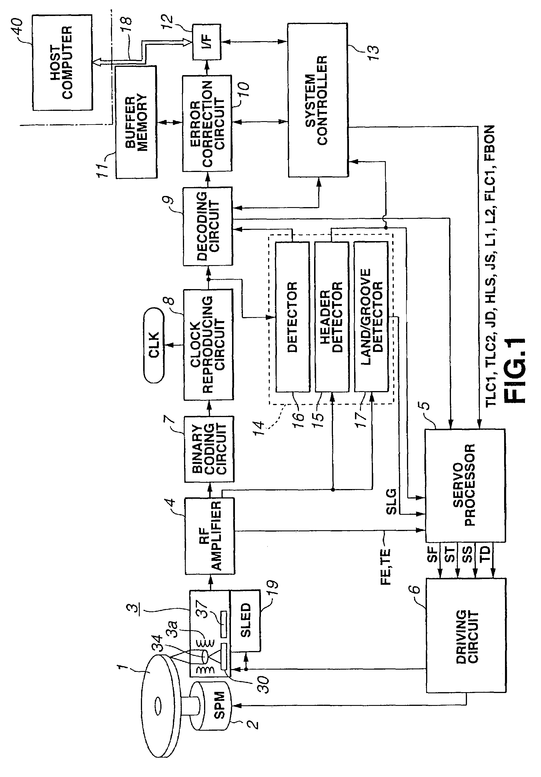
[0025]Referring to FIG. 1, a disc driving apparatus according to the first embodiment of the present invention, adapted for recording and reproducing the information for a loaded optical disc 1, includes a spindle motor (SPM) 2, an optical pickup 3, a biaxial mechanism 3a, a RF amplifier 4, a servo processor 5, a driving circuit 6, a binary coding circuit 7, a clock reproducing circuit 8, a decoder circuit 9, an error correction circuit 10, a buffer memory 11, a data interface 12, a system controller 13, a block for RAM 14, a header detector 15, a PID detector 16, a land / groove detector 17, an external data bus 18, a sled mechanism 19, a laser diode 30, an objective lens 34 and a photodetector 37, and is connected over an external data bus ...


PUM

PropertyMeasurementUnit
accelerationaaaaaaaaaa
polarityaaaaaaaaaa
distanceaaaaaaaaaa

Abstract

A disc driving apparatus and an information readout method according to the present invention realize optimum servo control of a readout unit in reading out the information from a recording medium having lands and grooves. The disc driving apparatus includes a unit for correcting tracking error signals, a unit for inverting signals corrected by the correcting unit to generate inverted tracking error signals, a unit for detecting which of the lands and the grooves the readout unit is scanning, and a unit for selecting the tracking error signals or the inverted tracking error signals according to the results of detection by the detection unit to tracking-control the readout unit by the selected signals.

Description

TECHNICAL FIELD[0001]This invention relates to a disc driving apparatus, comprised of a disc-shaped recording medium, on which the information is to be recorded or from which the information is to be reproduced, and to an information readout method.BACKGROUND ART[0002]Conventional compact discs (CDs) or DVD-ROMs are optical discs employing a pit recording system. An optical pickup is caused to sweep along a track including pits, and the light reflected therefrom is measured to reproduce the information recorded by the pits. Up to now, tracking error signals having the same polarity at all times are produced according to the amount of deviation of the optical pickup from a target track, so that these tracking error signals have directly been used for tracking servo control, referred to below simply as tracking control.[0003]However, when reading out the information from an optical disc, including lands and grooves, such as DVD-RAM, the tracking error signals are inverted in polarity ...

Claims


Application Information

Patent Timeline
Patent Type & Authority Patents(United States)
IPC IPC(8): G11B7/09G11B7/007
CPCG11B7/00718G11B7/0901G11B7/0908G11B7/094G11B7/004
Inventor TAKAOKA, MUNEHISAHAYASHI, KAZUYUKI
Owner SONY CORP
Why Eureka
Try Eureka