
PCI-express to PCI/PCI X translator

a technology of pci-express and translator, applied in the direction of electric digital data processing, instruments, etc., can solve the problems that the bandwidth and scalability limits of emerging and future computer systems will exceed, the time and cost of designing these replacement pci-express interface circuits may impede the manufacture and sale of pci express devices, and the time and cost of designing these replacement pci-express interface circuits may impede the manufacture and sale of p

Active Publication Date: 2007-12-25
RENESAS ELECTRONICS AMERICA
View PDF15 Cites 24 Cited by
  • Summary
  • Abstract
  • Description
  • Claims
  • Application Information

AI Technical Summary

Benefits of technology

"The patent describes an apparatus that can convert a PCI / PCI X device into a PCI-Express device. It includes a first circuit that receives and translates the first data into PCI formatted data. There is also a PCI data bus and a second circuit that receives the PCI formatted data from the first circuit through the PCI data bus. The second circuit then translates the data into PCI-Express formatted data. This allows for seamless communication between PCI and PCI-Express devices."

Problems solved by technology

However, demands of emerging and future computer systems will exceed the bandwidth and scalability limits that are inherent in PCI bus implementations.
The time and cost for designing these replacement PCI-Express interface circuits may impede the manufacture and sale of computer systems such as that shown in FIG. 4.
And the time and cost for designing these replacement PCI-Express interface circuits may impede the manufacture and sale of PCI Express devices such as that shown in FIG. 4.

Method used


Image

  • PCI-express to PCI/PCI X translator
  • PCI-express to PCI/PCI X translator
  • PCI-express to PCI/PCI X translator

Examples


Embodiment Construction

[0026]FIG. 6 is a block diagram of a computer system that employs one embodiment of the present invention. The present invention will be described with reference to a computer system, it being understood that the present invention should not be limited thereto. In other words, the present invention may be employed in systems (e.g., communication systems) other than computer systems.

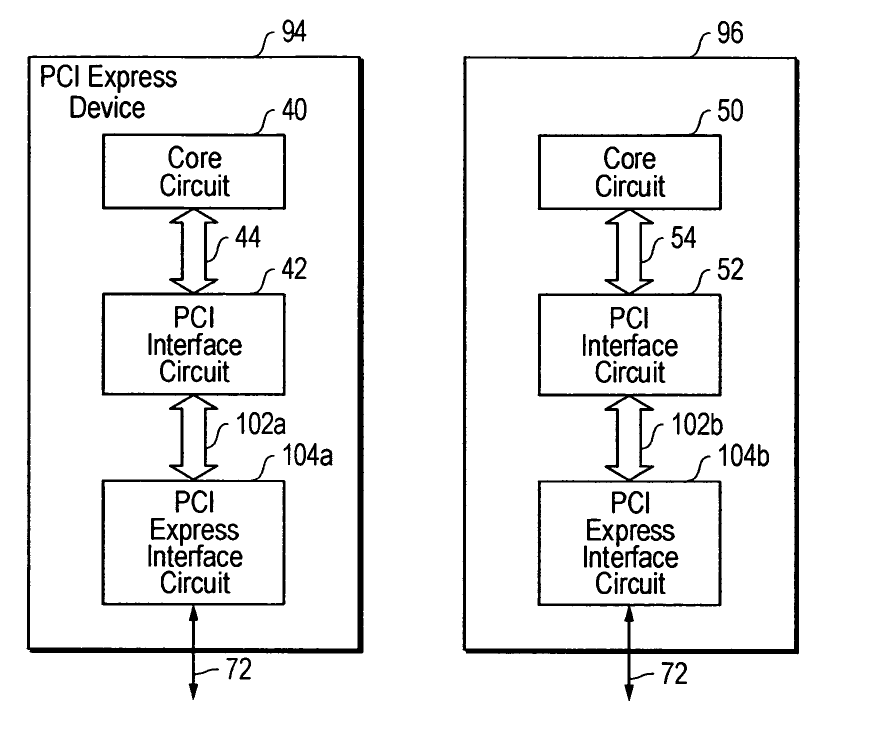
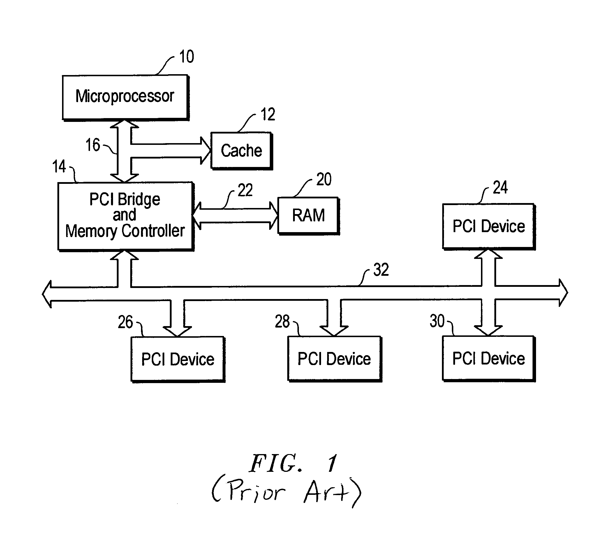
[0027]FIG. 6 is the computer system shown in FIG. 1 with the PCI bridge 14, PCI devices 24, 26, 28 and 30, and PCI bus 32 replaced by PCI-Express bridge 58, PCI-Express devices 94-100, and PCI-Express buses 72. PCI-Express Specification defines the signaling and protocol used by PCI-Express devices 94, 96, 98 and 100 to enable communication with each other and with PCI-Express bridge 58 via PCI-Express buses 72. PCI-Express bridge 58 and PCI-Express buses 72 in FIGS. 4 and 6 may be identical. The present invention may be implemented in one or more of the PCI devices 94-100. For purposes of explanation onl...


PUM


Abstract

An apparatus for converting a PCI / PCI X device into a PCI-Express device. The apparatus may include a first circuit configured to receive first data, wherein the first circuit is configured to translate the first data into PCI formatted data. The apparatus may also include a PCI data bus and a second circuit coupled to the first circuit via the PCI data bus. The second circuit is configured to receive the PCI formatted data from the first circuit via the PCI data bus. The second circuit is configured to translate the PCI formatted data received from the first circuit into PCI-Express formatted data. However, the PCI data bus transmits data between only the first and second circuits.

Description

BACKGROUND OF THE INVENTION[0001]Computer systems include devices such as microprocessors, main memory, disk drives, network adaptors, etc., that communicate with each other via data buses. Typical computer systems include a system bus, a memory bus, and a local bus. FIG. 1 is a block diagram illustrating a computer system employing several devices coupled together via a system bus, a memory bus, and a PCI bus. More particularly, FIG. 1 shows a microprocessor 10, cache 12, and PCI bridge / memory controller (hereinafter PCI bridge) 14 coupled together via system bus 16. PCI bridge could be implemented in one or multiple devices. Main memory 20 is also included; however main memory 20 is coupled to PCI bridge 14 via memory bus 22. Additionally, FIG. 1 shows PCI bridge 14 coupled to PCI devices 24, 26, 28 and 30 via PCI bus 32. It is noted that two devices can be coupled together directly or indirectly. For example, PCI device 24 is coupled to PCI device 30.[0002]PCI Local Bus Specifica...

Claims


Application Information

Patent Timeline
Patent Type & Authority Patents(United States)
IPC IPC(8): G06F13/36G06F13/00G06F13/38
CPCG06F13/385
Inventor SAKURAI, TOSHIMISHOU, JINHUNTENG, PETER CHU TIN
Owner RENESAS ELECTRONICS AMERICA
Learn More