
Disk drive with head-disk interaction sensor integrated with suspension

a head-disk and suspension technology, applied in the field of disk drives, can solve the problems of reducing the efficiency of head-disk interaction, affecting the speed of the drive, and affecting the speed of the drive, and reaching the limits of minimizing head-disk interaction

Inactive Publication Date: 2007-12-25
HITACHI GLOBAL STORAGE TECH NETHERLANDS BV
View PDF6 Cites 30 Cited by
  • Summary
  • Abstract
  • Description
  • Claims
  • Application Information

AI Technical Summary

Benefits of technology

"The present invention provides a technique for detecting slider fly-height modulation during a write process and inhibiting a write operation when slider fly-height modulation is detected. The suspension for a disk drive includes a head-disk interaction sensor that outputs a sensor signal when the slider contacts the disk of the disk drive. The sensor can be an accelerometer or a pressure sensor that senses the pressure between the flexure and the dimple or the piezoelectric material layer generated when the slider contacts the disk of the disk drive. A write-inhibit circuit is responsive to the sensor signal and inhibits the write operation of the disk drive. The filter circuit conditions the sensor signal and can have a narrow passband at about 200 kHz or a wider passband at about (200 kHz to 1.6 MHz) to include about (200 kHz to 1.6 MHz) or (200 kHz to 1.6 MHz)."

Problems solved by technology

When fly-height modulation occurs during a write process, that portion of data being written during slider jump-up can be lost because the data is not properly written on the disk due to greater than expected write-head-to-disk distance.
There is no current technique available for detecting fly-height modulation during a write process.
These approaches, however, will reach their respective limits for minimizing head-disk interaction as slider fly-height is further reduced.

Method used


Image

  • Disk drive with head-disk interaction sensor integrated with suspension
  • Disk drive with head-disk interaction sensor integrated with suspension
  • Disk drive with head-disk interaction sensor integrated with suspension

Examples


Embodiment Construction

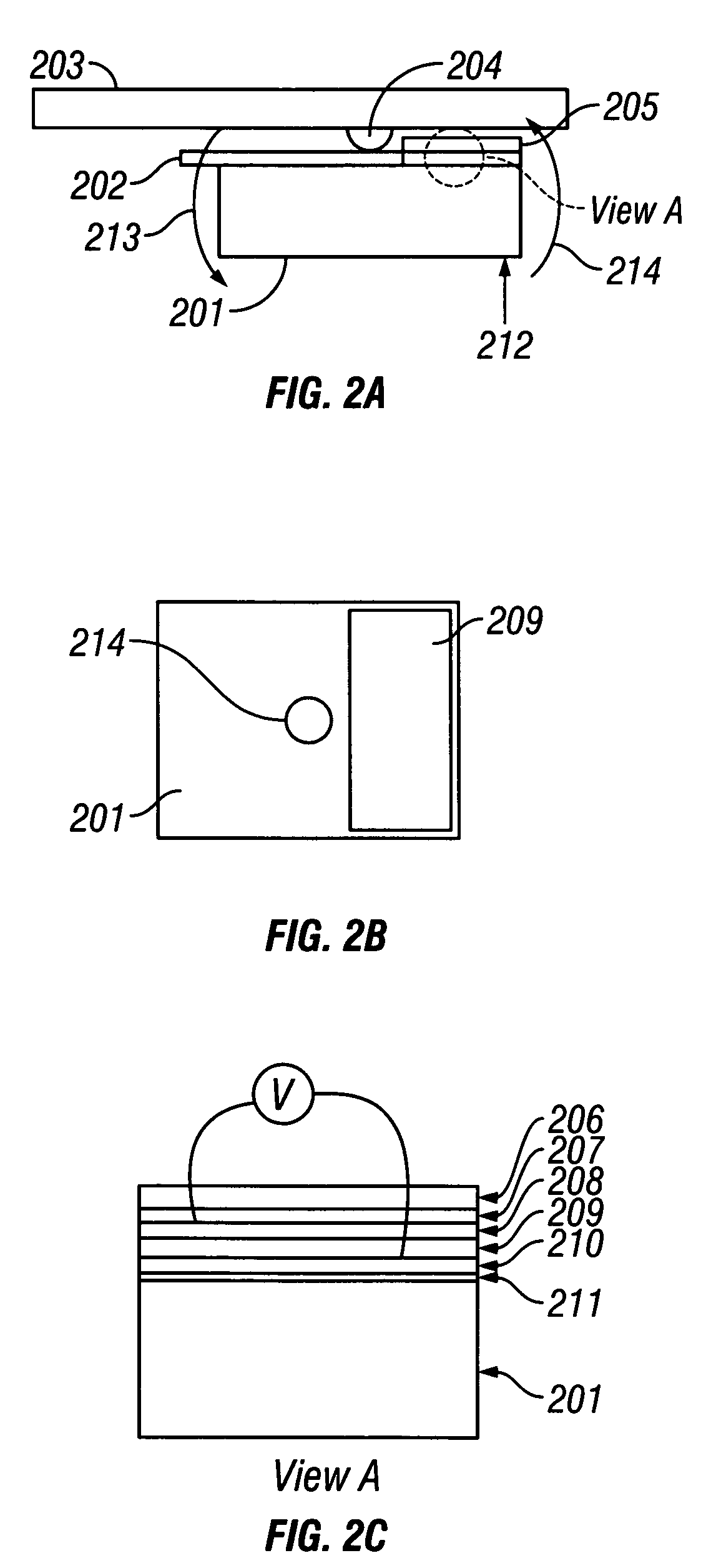
[0026]The present invention detects head-disk interaction in an HDD by using at least one sensor that is integrated with suspension. Slider motion caused by Head-Disk Interference (HDI) is detected by using a force (or pressure) sensor for monitoring the force (or pressure) between the back of the slider and the suspension dimple, and / or by using an accelerometer for measuring the acceleration of the slider. Both the pressure sensor and the acceleration sensor are integrated with a suspension having a laminated flexure.

[0027]The signal output from the sensors includes both air-flow-related noise and write-current-related noise. Noise that is caused by air-flow typically has a very low frequency component, i.e., less than 20 kHz. Noise that is caused by write current typically has a very high frequency, i.e., greater than 2 Mhz. Accordingly, the present invention passes the frequency component at the pitch mode frequency of the slider at approximately 200 kHz, and at the first bendin...


PUM

PropertyMeasurementUnit
pitch frequencyaaaaaaaaaa
frequencyaaaaaaaaaa

Abstract

A Hard Disk Drive (HDD) includes a write-inhibit signal that is generated by a head-disk interaction sensor during a write process that is integrated with a suspension of the HDD when fly-height modulation of the slider is detected during a write process. The suspension load beam includes a dimple and a laminated flexure. The laminated flexure includes a surface that is adapted to receive a slider and a surface that is adapted to contact the dimple. The head-disk interaction sensor is fabricated as part of the laminations of the flexure. The head-disk interaction sensor can be an accelerometer that senses an acceleration of the flexure when the slider contacts the disk of the disk drive and / or a pressure sensor that senses a pressure between the flexure and the dimple when the slider contacts the disk. A write-inhibit circuit is responsive to the sensor signal by inhibiting the write process.

Description

CROSS-REFERENCE TO RELATED APPLICATION[0001]The present application is related, co-assigned and concurrently filed patent application Ser. No. 10 / 664,295 entitled “Head-Disk Interaction Sensor Integrated With Suspension,” which is incorporated by reference herein.BACKGROUND OF THE INVENTION[0002]1. Field of the Invention[0003]The present invention relates to disk drives. More particularly, the present invention relates to a sensor system for improving write operations for a hard disk drive (HDD).[0004]2. Description of the Related Art[0005]FIG. 1 shows an exemplary hard disk drive (HDD) 100 having a magnetic read / write (R / W) head (or a recording slider) 101 that includes, for example, a tunnel-valve read sensor, that is positioned over a selected track on a magnetic disk 102. As the fly-height of slider 101 becomes smaller, the chance of slider 101 hitting asperities on disk 102, for example, disk defects, particles, and / or lubricant bumps, becomes greater, resulting in a higher pro...

Claims


Application Information

Patent Timeline
Patent Type & Authority Patents(United States)
IPC IPC(8): G11B27/36G11B19/04G11B5/012G11B5/02G11B5/48G11B5/60G11B19/14
CPCG11B5/4826G11B19/04G11B5/6005G11B5/4833G11B5/012
Inventor HIRANO, TOSHIKINAYAK, ULLAL VASANTZENG, QINGHUA
Owner HITACHI GLOBAL STORAGE TECH NETHERLANDS BV
Learn More