Energy concentrator system and method

Inactive Publication Date: 2007-12-25
FIELDS JOHN G +1
View PDF5 Cites 2 Cited by
  • Summary
  • Abstract
  • Description
  • Claims
  • Application Information

AI Technical Summary

Benefits of technology

[0013]The use of a source in the shape of a circle and a thin line source allows the use of many different frequencies and wavelengths, both RF and others. Other phenomenologies, such as acoustics / sound, electromagnetic radiation at light frequencies and nuclear particles can be focused using this approach. In short, the reflective housing focuses divergent energy from elongated sources to a point and the elongated source configuration permits the use of a wide assortment of energy sources and high energy input for the point focus output.
[0014]The apparatus and methods of the present invention allow the use of antenna design to increase efficiency by increasing the capture within the system of divergent energy from the input or source and by focusing the energy to a point or point volume output and attenuating the energy loss to surrounding regions or volumes.

Problems solved by technology

Prior art systems which project energy into the body to destroy tumors, etc. typically suffer from the inability to precisely focus the energy at high concentrations inside the body and to destroy the target without injury to the surrounding tissue and skin.
RF energy offers the potential advantage of high power, but it is difficult to focus RF energy, and especially difficult to focus such energy without absorption in surrounding media.
More specifically, the prior art of focusing RF energy to a point / point volume from a source has been a challenge because of the divergent nature of the radiation pattern and frequency wavelength.
In some cases the healthy tissue is heated severely and / or experiences severe side effects.
It is thought to be as the result of these difficulties that RF systems have not been used successfully for applications such as non-invasive surgery.

Method used


Image

  • Energy concentrator system and method
  • Energy concentrator system and method
  • Energy concentrator system and method

Examples


example

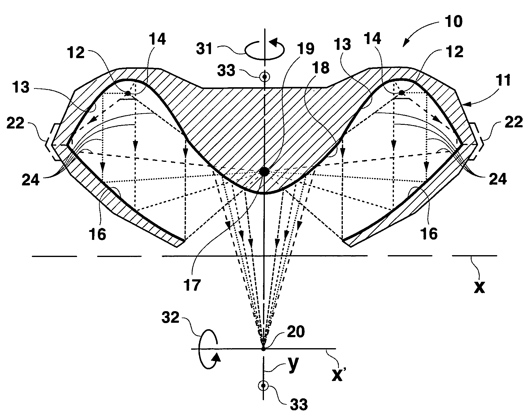
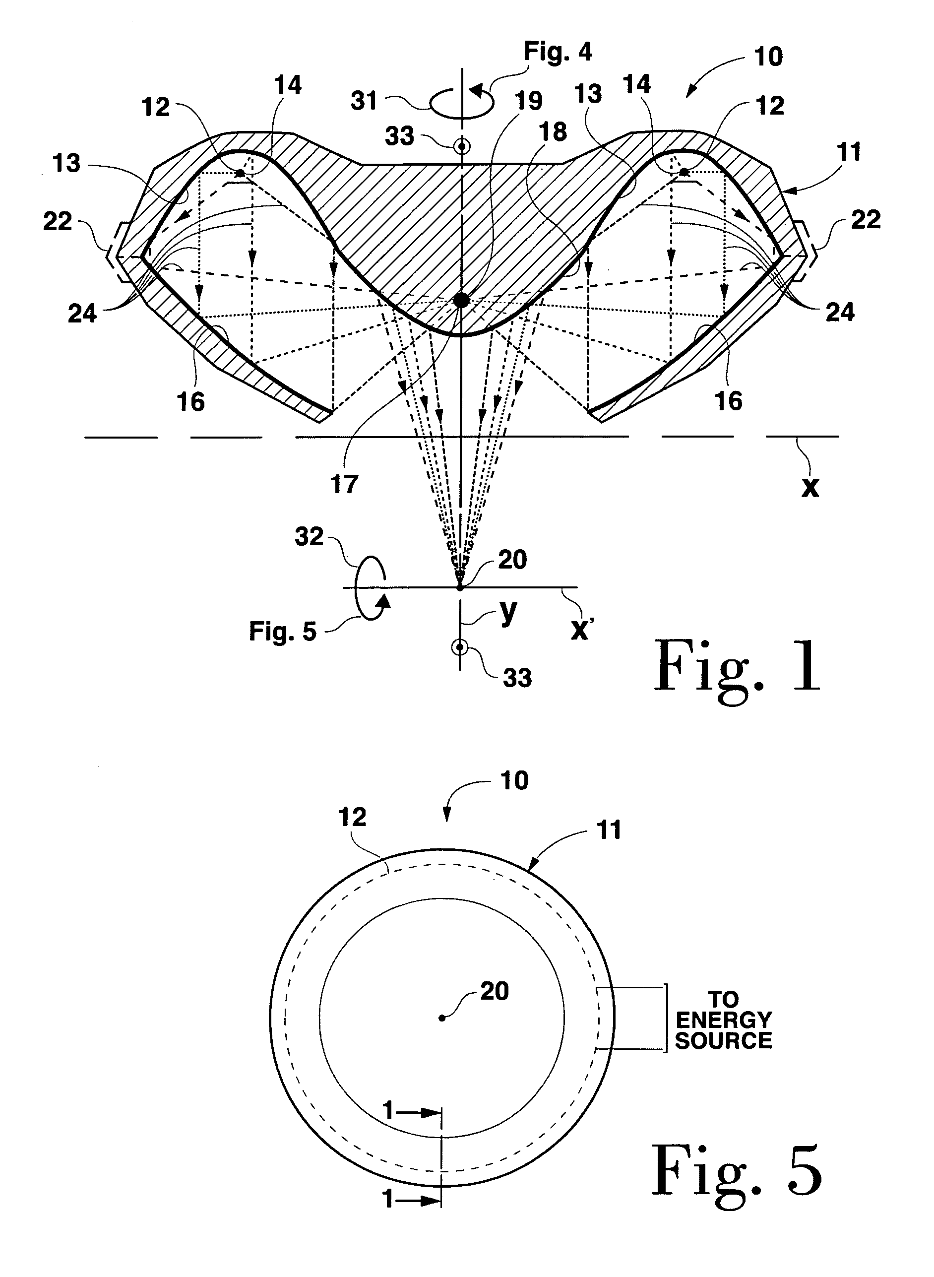
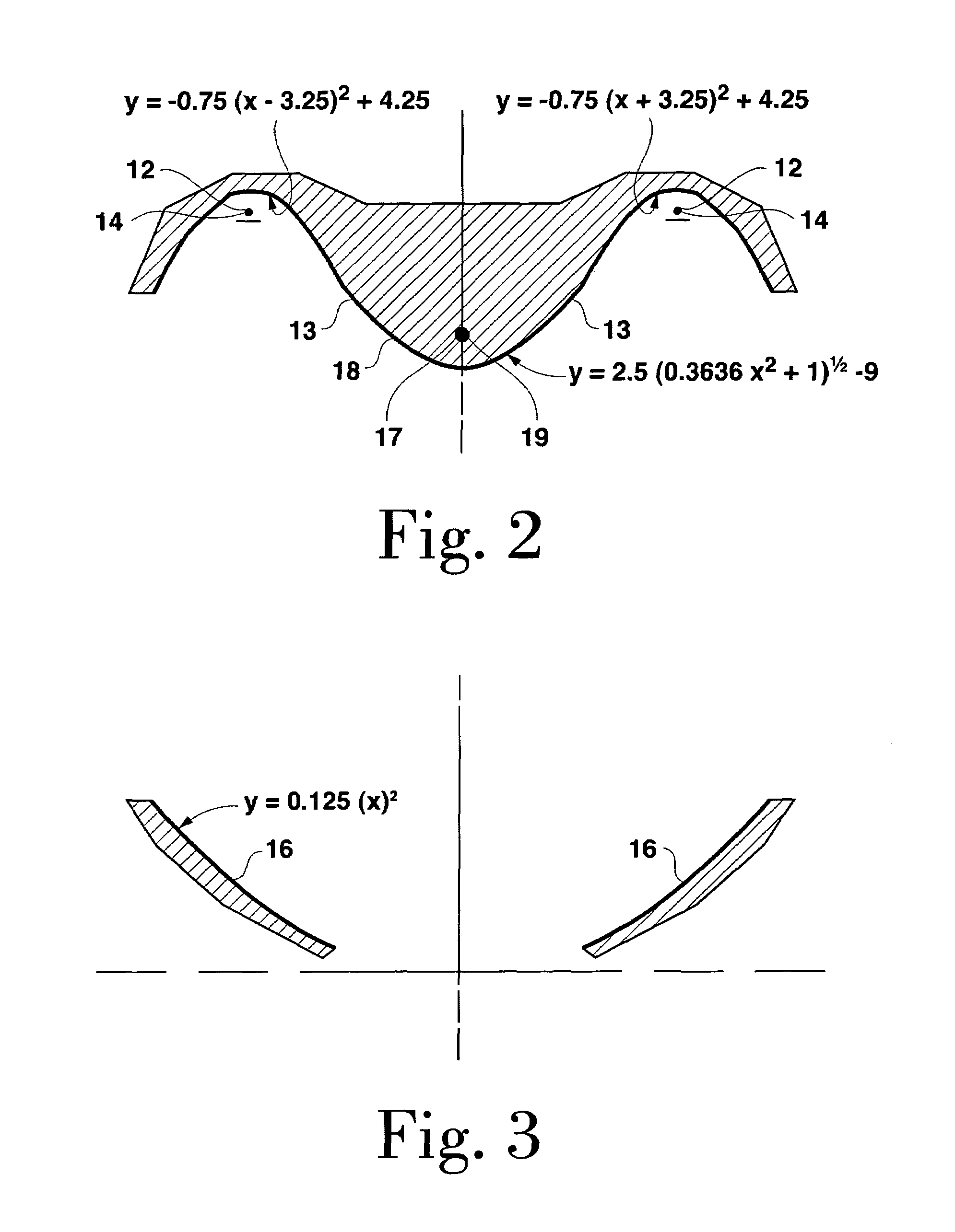
[0040]An exemplary circular reflector unit 10 of the type depicted in FIG. 4 and which effects the above described energy concentration, expressed mathematically, comprises two primary (or first) parabolic reflectors 13—13 of equation y=−0.75 (x−3.25)2+4.25 (left side parabolic, FIGS. 1 and 2) and y=−0.75 (x+3.25)2+4.25 (right side parabolic, FIGS. 1 and 2); two secondary (or second) parabolic reflectors 16—16, both of the equation y=0.125x2 (FIGS. 1 and 3); and a hyperbolic reflector 18 of equation y=2.5(0.3636x2+1)1 / 2−1 (FIGS. 1 and 2).


PUM


Abstract

Reflective apparatus and method by which energy is radiated in divergent fashion from an elongated source and is reflected by a first parabolic reflector as a paraxial beam, focused by a second parabolic reflector onto a hyperbolic reflector and reflectively concentrated by the hyperbolic reflector at a focus at a distance from the source. The system also shields the point from extraneous radiation that would not be concentrated at the point. In one exemplary application, electromagnetic energy radiated from a point or linear source is focused by the multiple reflector system to a very high concentration at a point, for example, within an organism such as a human or animal body.

Description

BACKGROUND OF THE INVENTION[0001]1. Field of the Invention[0002]The present invention relates in general to systems for concentrating energy and, more particularly, to systems for concentrating electromagnetic energy.[0003]The present invention also relates to systems and methods for concentrating energy for the purpose of destroying tumors and other undesirable growths.[0004]2. Description of the Related Art[0005]Prior art systems which project energy into the body to destroy tumors, etc. typically suffer from the inability to precisely focus the energy at high concentrations inside the body and to destroy the target without injury to the surrounding tissue and skin.[0006]RF energy offers the potential advantage of high power, but it is difficult to focus RF energy, and especially difficult to focus such energy without absorption in surrounding media. More specifically, the prior art of focusing RF energy to a point / point volume from a source has been a challenge because of the div...

Claims


Application Information

Patent Timeline
IPC IPC(8): A61N7/00
CPCG10K11/28A61B18/18
Inventor FIELDS, JOHN G.DALTON, PHILIP A.
Owner FIELDS JOHN G
Why Eureka
Try Eureka