
Satellite antenna alignment device and method

a technology for satellite antennas and alignment devices, which is applied in the direction of mechanical measuring arrangements, instruments, and using mechanical means, etc., can solve the problems of inconvenient installation, cumbersome process, and inconvenient installation

Inactive Publication Date: 2007-12-18
WALLACE RODNEY LEROIE
View PDF19 Cites 4 Cited by
  • Summary
  • Abstract
  • Description
  • Claims
  • Application Information

AI Technical Summary

Benefits of technology

"The present invention is a device for aligning a satellite antenna. It includes a grooved cylindrical sleeve, a raised azimuth indicator ring, a magnetic or digital compass, and a bubble level. The device is designed to simplify the process of aligning a satellite antenna and improve the accuracy of the alignment."

Problems solved by technology

The installation of a satellite antenna dish has historically been a laborious and time-consuming process that typically involves two individuals to: (1) use a bubble level to horizontally stabilize and position a mounting pole which supports the antenna dish, (2) estimate the desired azimuth by using a compass to determine the local azimuth heading of the North Magnetic Pole, (3) manually turn the antenna dish to the estimated local azimuth heading of the North Magnetic Pole, (4) manually tilt the antenna dish with a protractor to align the antenna dish along the recommended elevation for the installation location, (5) use an electronic sensing device to determine the azimuth heading along which the strongest satellite broadcast signal strength will be received, and (6) manually turn the antenna dish to that azimuth heading along which the strongest satellite broadcast signal strength will be received.
However the support arm can only move relative to the antenna reflector and any such movement or misalignment will cause or contribute to an incorrect alignment with respect to the desired satellite.
Further, devices that are affixed to a support arm or to the antenna itself are not easily visible to the installer during the installation and alignment process.
Further still, all of these devices must be physically attached and secured to the antenna or the support arm which means that the alignment takes place after the antenna is placed on the mounting pole, a cumbersome, manhandling process at best.
Finally, most of these devices do not lend themselves to easy detachment or mobility which, in turn, limits the likelihood of their repetitive use for multiple installations.
While it is possible for one installer to use this method, it is impractical in view of the numerous trips required to check the signal strength presentation, return to the antenna to make adjustments, check the signal strength presentation again, return to the antenna to make another adjustment, etc.
Whether the installation is done by one person or two, the process is time-consuming and / or costly.
While this solution may serve to permit installation by only one person, practitioners have reported that the user may not always discern the changes in the flash rate of the LED as the signal strength increases or decreases giving rise to positioning at less than optimal alignment.
Further, this method is only effective when the antenna alignment is close to its desired position; it cannot be used to initially position the antenna.
However, even the “Dish-Aligner” requires the use of a set top box to fine-tune the alignment for optimal positioning so the problem of a two-person installation team remains.

Method used


Image

  • Satellite antenna alignment device and method
  • Satellite antenna alignment device and method
  • Satellite antenna alignment device and method

Examples


embodiment

Preferred Embodiment

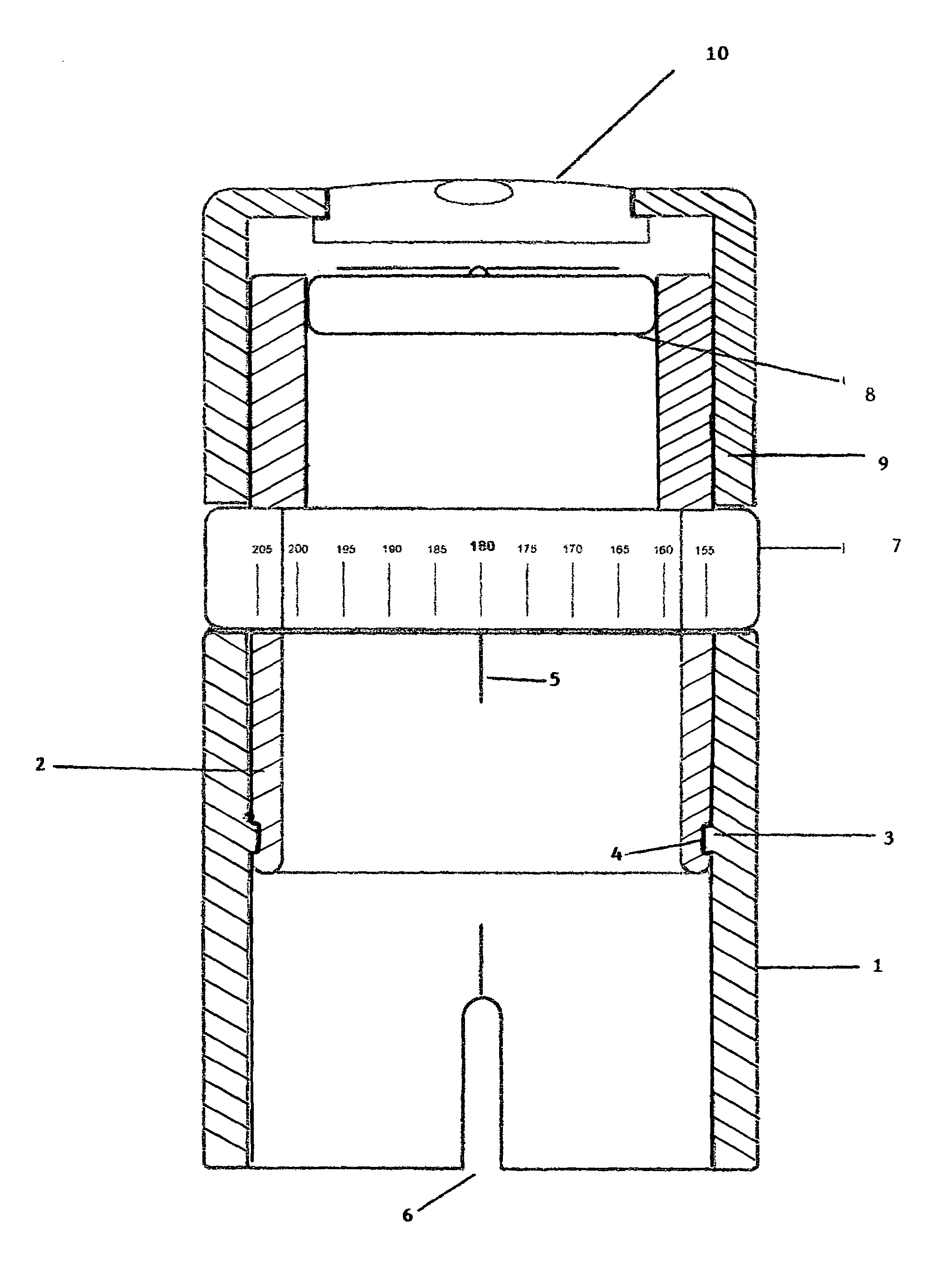
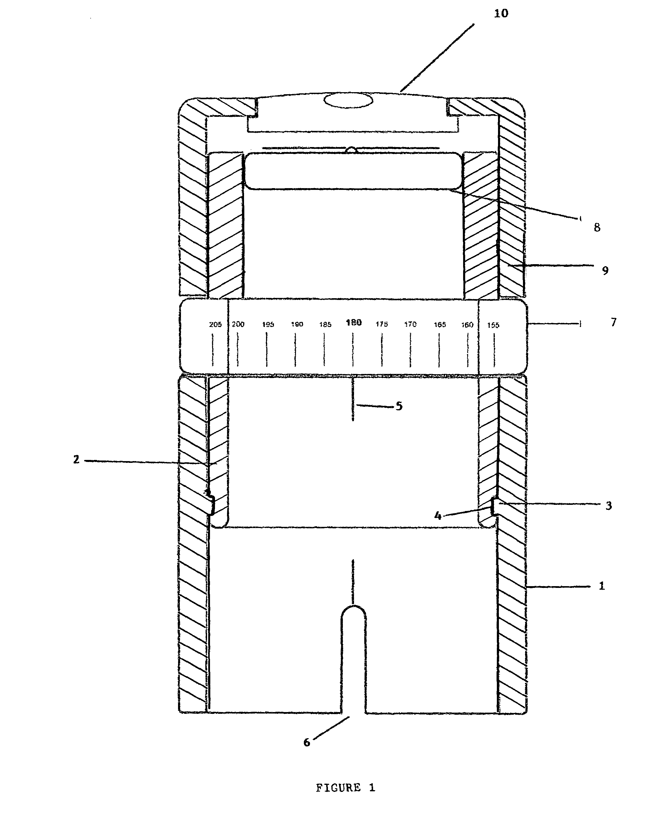
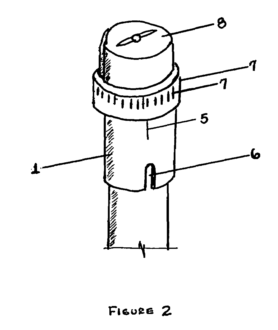
[0043]In the preferred embodiment of this invention, the satellite antenna installer would contact the manufacturer of the satellite antenna dish and / or the operator of the satellite broadcasting or rebroadcasting the desired satellite television, radio, or Internet signal(s) to obtain the optimal azimuth and elevation settings for the geographic location of the site of the intended installation. The installer would then rotate cylindrical insert 2 with respect to cylindrical sleeve 1 until the value of the optimal azimuth setting on azimuth indicator ring 7 is exactly aligned with azimuth indicator mark 5. Since cylindrical insert 2 fits tightly inside cylindrical sleeve 1, there is little or no chance of inadvertent movement. Nonetheless, other embodiments of this invention contemplate methods of locking the position of cylindrical insert 2 with respect to cylindrical sleeve 1.

[0044]After positioning cylindrical insert 2 and cylindrical sleeve 1 with the optima...


PUM


Abstract

An alignment device and method for aligning an antenna with a satellite. The device includes a grooved cylindrical sleeve inserted into a ridged cylindrical sleeve, a raised azimuth indicator ring and a magnetic or digital compass mounted upon the grooved cylindrical sleeve, and a bubble level mounted on a capped cylindrical sleeve that fits over the grooved cylindrical sleeve. A known value of optimal azimuth alignment is offset from the North Magnetic Pole so that a reference and alignment mark may be placed on the antenna mounting pole. This alignment device and method eliminate the need for two technicians and eliminate the need for a signal strength measuring device.

Description

FEDERALLY SPONSORED RESEARCH[0001]Not ApplicableSEQUENCE LISTING OR PROGRAM[0002]Not ApplicableBACKGROUND[0003]1. Field of Invention[0004]This present invention generally relates to satellite antenna alignment devices and more particularly to a satellite antenna alignment device which permits an installer to align a satellite antenna so as to receive the strongest signal in a particular geographic location from a particular satellite in geosynchronous orbit.[0005]2. Description of the Related Art[0006]Consumers are currently using satellite antennas to receive broadcast or rebroadcast signals from satellites owned and / or operated by companies that provide satellite television, radio, or Internet services. Examples of companies providing satellite broadcast services include, without limitation, SBC Global™, COMCAST™, DISH Network™, DIRECT TV™, and PRIMESTAR™. Generally, these companies will utilize a satellite in geosynchronous orbit and which they own or lease to transmit television...

Claims


Application Information

Patent Timeline
Patent Type & Authority Patents(United States)
IPC IPC(8): G01C17/02G01C9/36
CPCH01Q1/125
Inventor WALLACE, RODNEY LEROIE
Owner WALLACE RODNEY LEROIE
Learn More