
Method and system for providing a stable spin filter

a spin filter and stable technology, applied in the field of magnetic recording technology, can solve problems such as degrading the signal of such a spin filter

Inactive Publication Date: 2007-12-11
WESTERN DIGITAL TECH INC
View PDF8 Cites 152 Cited by
  • Summary
  • Abstract
  • Description
  • Claims
  • Application Information

AI Technical Summary

Benefits of technology

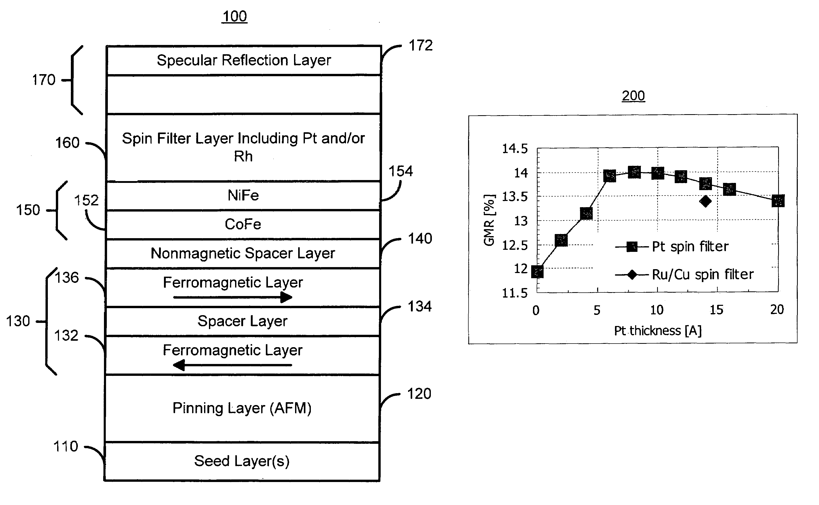
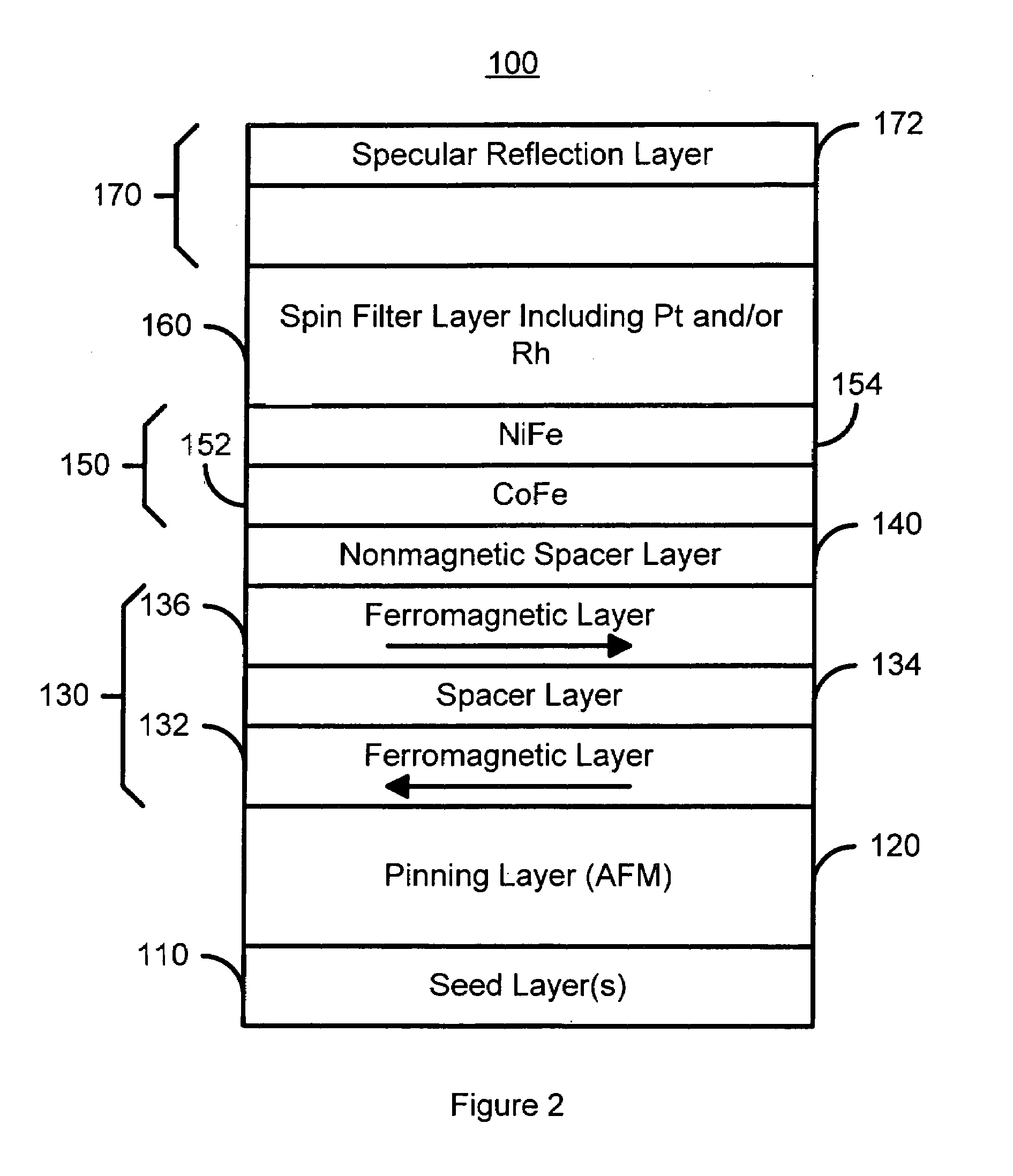
The present invention provides a method and system for creating a spin filter. This involves using a pinned layer, a free layer, and a conductive nonmagnetic spacer layer between them. Additionally, a spin filter layer and a capping layer are used. The spin filter layer is adjacent to the free layer and includes materials such as Pt and Rh. The capping layer has a specular reflection layer that allows for the reflection of current carriers. The system and method provide a stable spin filter.

Problems solved by technology

Although such a conventional spin filter may address some of the issues described above, the signal from such a spin filter may be degraded.

Method used


Image

  • Method and system for providing a stable spin filter
  • Method and system for providing a stable spin filter
  • Method and system for providing a stable spin filter

Examples


Embodiment Construction

[0015]The present invention relates to an improvement in magnetic recording technology. The following description is presented to enable one of ordinary skill in the art to make and use the invention and is provided in the context of a patent application and its requirements. Various modifications to the preferred embodiment will be readily apparent to those skilled in the art and the generic principles herein may be applied to other embodiments. Thus, the present invention is not intended to be limited to the embodiment shown, but is to be accorded the widest scope consistent with the principles and features described herein.

[0016]The present invention provides a method and system for providing a spin filter. The method and system comprise providing a pinned layer, providing a free layer, and providing a conductive nonmagnetic spacer layer residing between the pinned layer and the free layer. The method and system also comprise providing a spin filter layer and a capping layer on t...


PUM

PropertyMeasurementUnit
thickaaaaaaaaaa
thicknessaaaaaaaaaa
thicknessaaaaaaaaaa

Abstract

A method and system for providing a spin filter is disclosed. The method and system include providing a pinned layer, a free layer, and a conductive nonmagnetic spacer layer between the pinned layer and the free layer. The method and system also include providing a spin filter layer and a capping layer on the spin filter layer. The spin filter layer is adjacent to the free layer. The spin filter layer is on an opposite side of the free layer as the nonmagnetic spacer layer and includes at least Pt and / or Rh. The capping layer has a specular reflection layer therein. In one aspect, the specular reflection layer allows specular reflection of current carriers traveling from the spin filter layer to the specular reflection layer. In another aspect, the specular reflection layer includes at least Ta, Ti, Zr, Hf, Nb, Al, Mo, W, Si, Cr, V, Ni, Co, and Fe.

Description

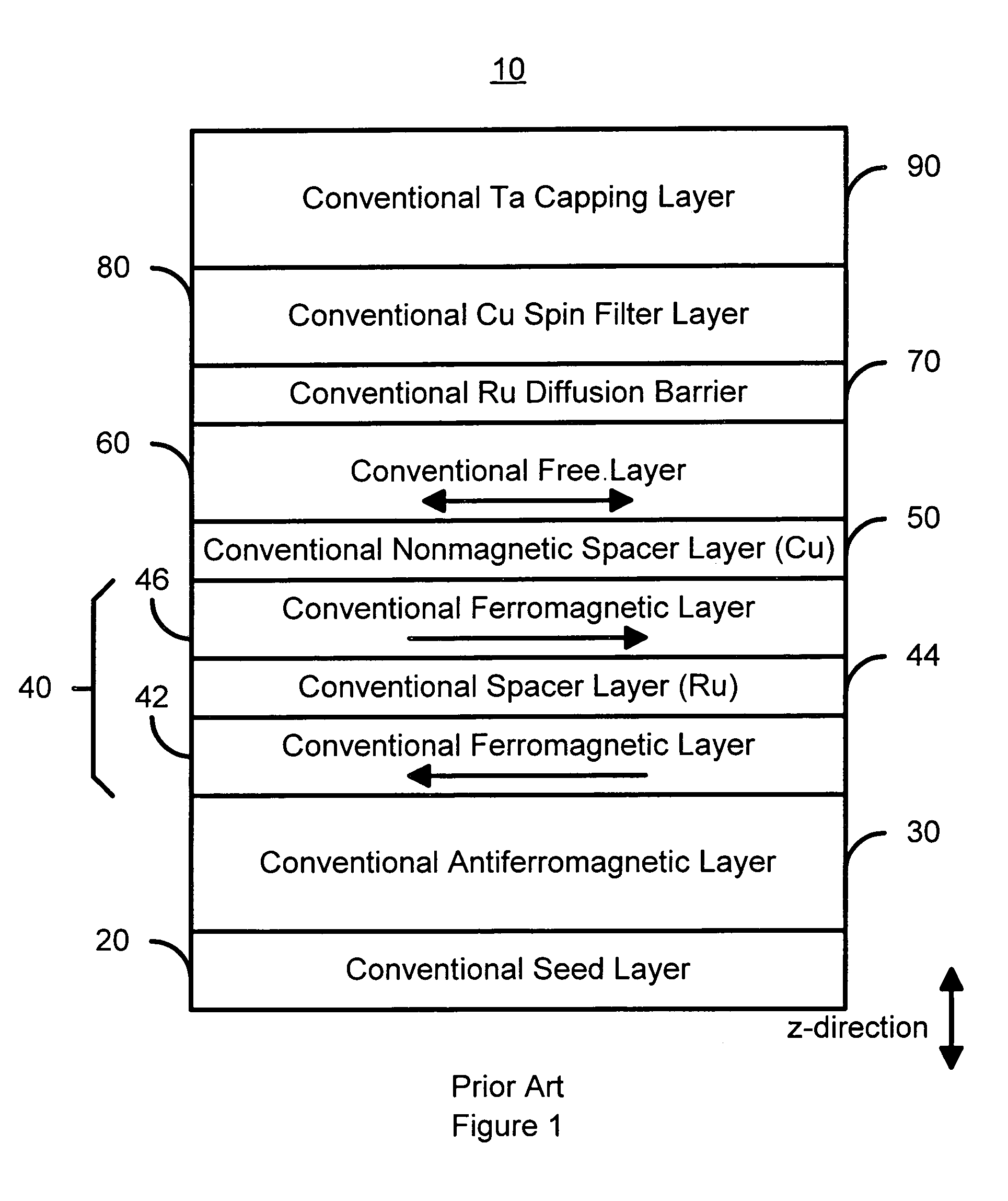
FIELD OF THE INVENTION[0001]The present invention relates to magnetic recording technology, and more particularly to a method and system for providing an improved spin filter.BACKGROUND OF THE INVENTION[0002]In the drive toward higher density recording media, spin filters have become of interest for use in magnetoresistive (MR) read heads. FIG. 1 is a diagram of a conventional spin filter 10 that may be used in reading high density recording media. In general, the conventional spin filter 10 would be incorporated into a MR read head (not explicitly shown), which would include leads and other electronics to drive current through the conventional spin filter 10 during reading. In such an application, current is generally driven in the current perpendicular to the plane (CPP) configuration. The CPP configuration is in the z-direction depicted in FIG. 1.[0003]The conventional spin filter 10 includes a conventional seed layer 20, a conventional antiferromagnetic (AFM) layer 30, a convent...

Claims


Application Information

Patent Timeline
Patent Type & Authority Patents(United States)
IPC IPC(8): G11B5/39G11B5/127
CPCB82Y25/00G01R33/093G11B5/3906H01F41/325H01F41/32H01L43/08H01F10/3272H01F10/3295H10N50/10
Inventor PARK, CHANG-MANFUNADA, SHINRANA, AMRITPAL S.MILOSLAVSKY, LENA
Owner WESTERN DIGITAL TECH INC
Learn More