
Catadioptric imaging system employing immersion liquid for use in broad band microscopy

a broad band microscopy and imaging system technology, applied in the field of optical imaging, can solve the problems of difficult design of microscopes designed to support immersion imaging for high resolution specimen imaging, inability to provide accurate imaging performance for light wavelengths below the range of approximately 400 nm,

Inactive Publication Date: 2007-12-11
KLA TENCOR TECH CORP
View PDF9 Cites 4 Cited by
  • Summary
  • Abstract
  • Description
  • Claims
  • Application Information

AI Technical Summary

Benefits of technology

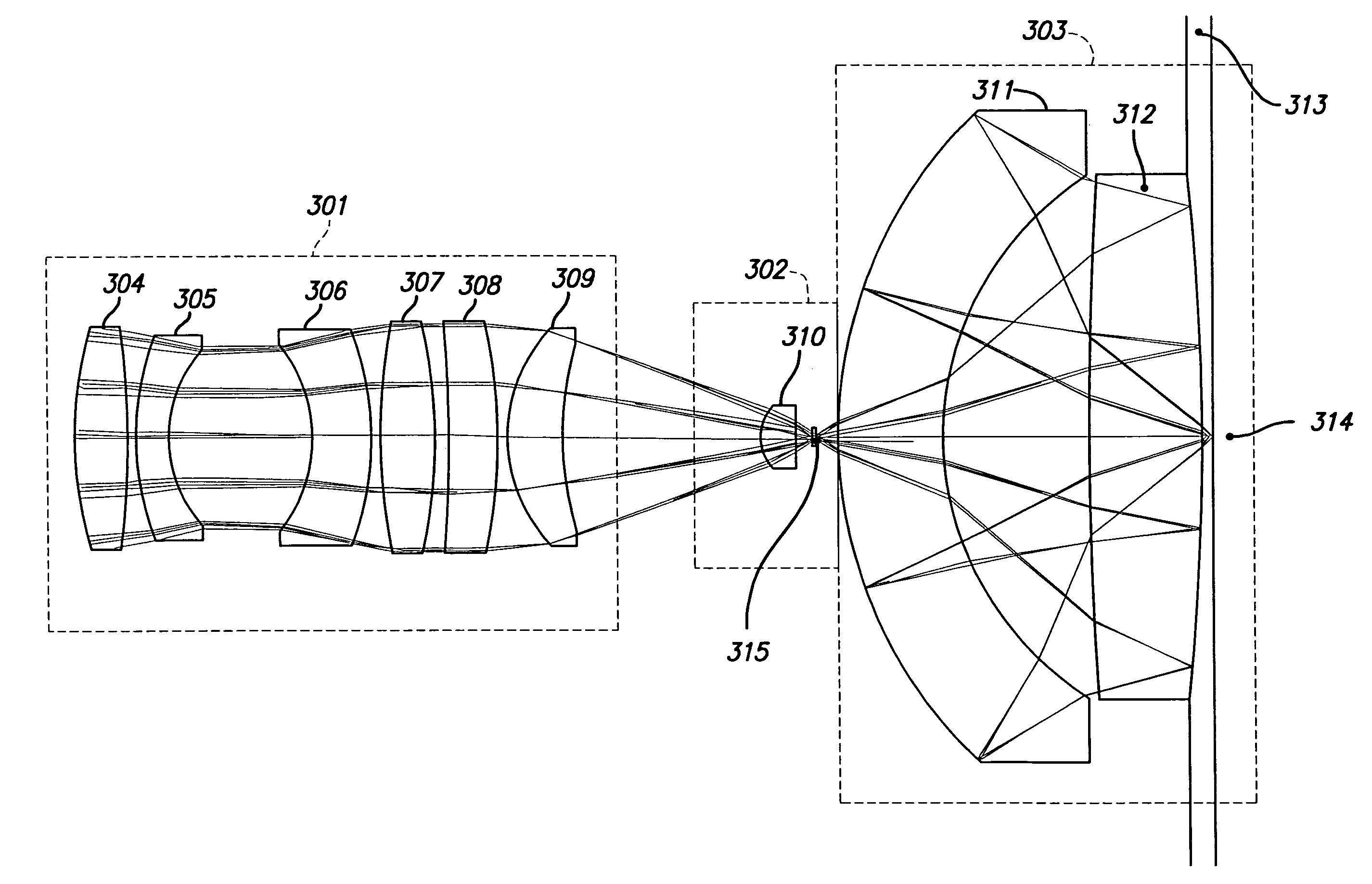
"The present invention provides an objective for inspecting a specimen using light energy with a wavelength in the range of 266 to 1000 nanometers. The objective comprises a focusing lens group, a field lens, a Mangin mirror arrangement, and an immersion substance. The objective can be used with a variable focal length optical system. The technical effects of the invention include improved inspection of specimens using focused light energy and controlled light energy, as well as the ability to insert additional optical elements."

Problems solved by technology

Furthermore, due to the nature and fragile properties associated with certain biological specimens, biological imaging systems frequently cannot use dry imaging whatsoever.
Microscopes designed to support immersion imaging can be difficult to design for high resolution specimen imaging.
Some available UV objectives can transmit light at wavelengths down to a wavelength of 340 nm, but these objectives do not provide accurate imaging performance for light wavelengths below the range of approximately 400 nm.
Such fluorescence excitation does not perform an inspection of the specimen and thus such an objective provides limited, if any, inspection functionality.
No immersion objectives are currently known that can support broad band inspection performance at light wavelengths below 400 nm.
Some dry objective designs may be highly corrected for broad band imaging at wavelengths below 400 nm, but none of these dry objective designs can be used in a standard microscope system.
The dry objective designs are typically too large, have insufficient numerical aperture (NA), or have an insufficient field size.

Method used


Image

  • Catadioptric imaging system employing immersion liquid for use in broad band microscopy
  • Catadioptric imaging system employing immersion liquid for use in broad band microscopy
  • Catadioptric imaging system employing immersion liquid for use in broad band microscopy

Examples


Embodiment Construction

Available Dry Imaging Designs

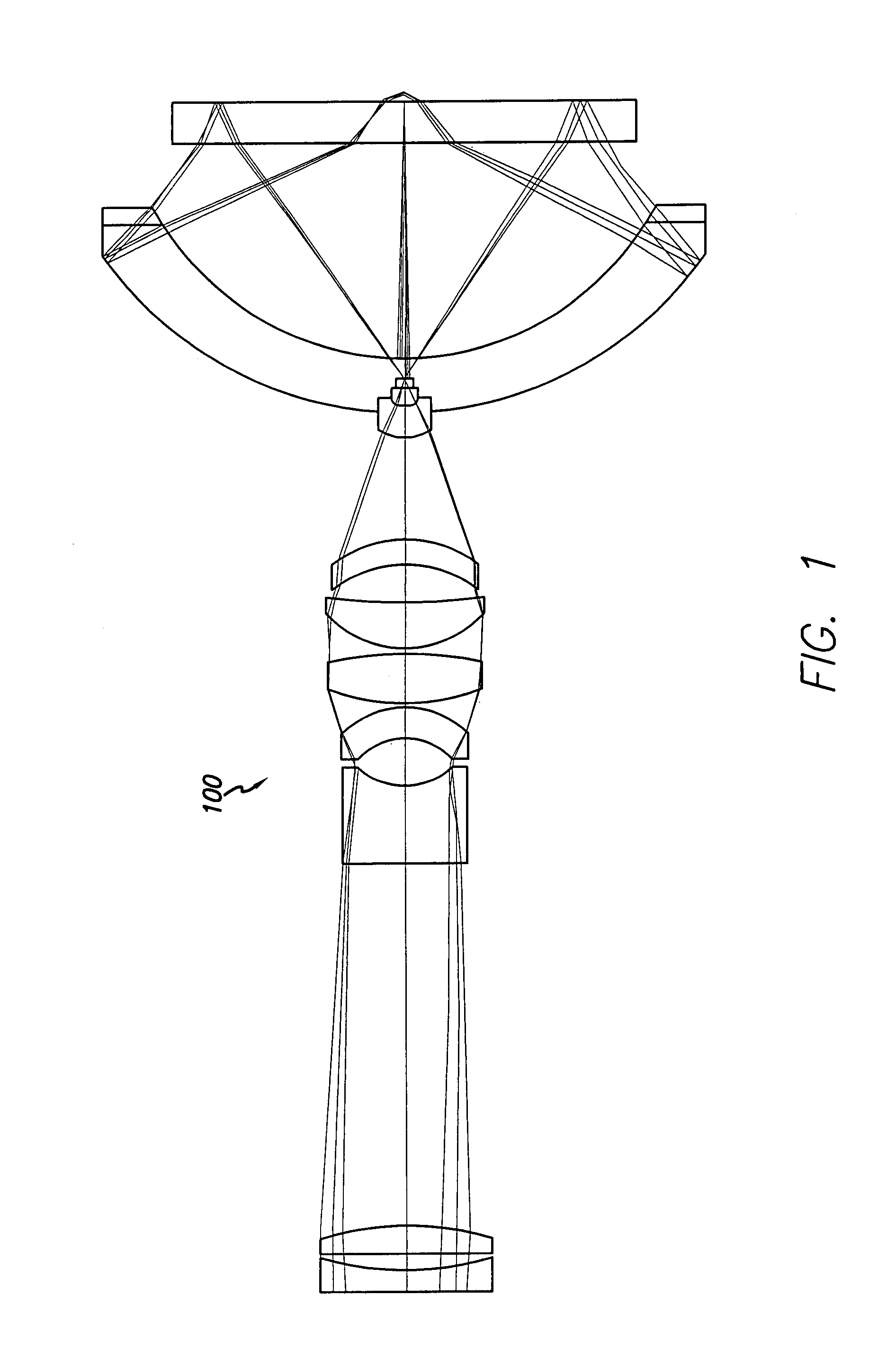
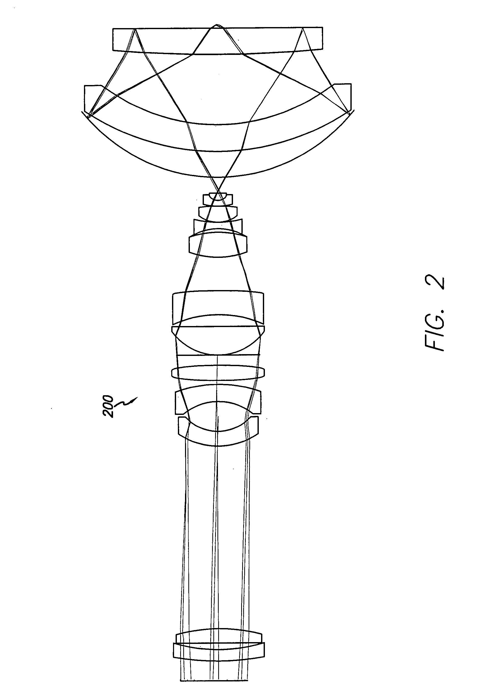
[0031]Two patents that disclose dry objective, broad band, highly UV corrected, high numerical aperture (NA) catadioptric systems are U.S. Pat. No. 5,717,518 to Shafer et al. and U.S. Pat. No. 6,483,638 to Shafer et al. Both represent dry imaging designs having certain advantageous inspection and imaging characteristics. A representative illustration of a catadioptric design 100 in accordance with the teachings of the '518 patent is presented in FIG. 1, which is similar to FIG. 1 of the '518 patent. A representative illustration of a catadioptric design 200 in accordance with the teachings of the '638 patent is presented in FIG. 2, which has similarities to FIG. 4 of the '638 patent.

[0032]U.S. Pat. No. 5,717,518 to Shafer et al. discloses a dry objective design capable of high NA, ultra broadband UV imaging. The high NA (up to approximately 0.9) system can be used for broadband bright field and multiple wavelength dark-field imaging. Certain issues exist...


PUM

PropertyMeasurementUnit
wavelengthaaaaaaaaaa
diameteraaaaaaaaaa
wavelengthaaaaaaaaaa

Abstract

A reduced size catadioptric inspection system employing a catadioptric objective and immersion substance is disclosed. The objective may be employed with light energy having a wavelength in the range of approximately 190 nanometers through the infrared light range, and can provide numerical apertures in excess of 0.9. Elements are less than 100 millimeters in diameter and may fit within a standard microscope. The objective comprises a focusing lens group, a field lens, a Mangin mirror arrangement, and an immersion substance or liquid between the Mangin mirror arrangement and the specimen. A variable focal length optical system for use with the objective in the catadioptric inspection system is also disclosed.

Description

[0001]This application is a continuation-in-part of U.S. patent application Ser. No. 10 / 646,073, entitled “Catadioptric Imaging System for Broad Band Microscopy,” inventors David G. Shafer, et al., filed Aug. 22, 2003, which is a continuation-in-part of U.S. patent application Ser. No. 10 / 434,374, entitled “High Performance Catadioptric Imaging System,” inventors David G. Shafer, et al., filed May 7, 2003, which claims the benefit of U.S. Provisional Patent Application Ser. No. 60 / 449,326, entitled “High Performance, Low Cost Catadioptric Imaging System,” filed Feb. 21, 2003.BACKGROUND OF THE INVENTION[0002]1. Field of the Invention[0003]The present invention relates generally to the field of optical imaging and more particularly to catadioptric optical systems used for microscopic imaging, inspection, and lithography applications.[0004]2. Description of the Related Art[0005]Many optical systems have the ability to inspect or image features on the surface of a specimen, such as insp...

Claims


Application Information

Patent Timeline
Patent Type & Authority Patents(United States)
IPC IPC(8): G02B17/08G02B17/02G02B21/02G02B21/04G02B21/33G03F7/20
CPCG02B17/023G02B17/0808G02B17/0812G02B17/0856G03F7/70341G02B21/02G02B21/04G03F7/70225G02B17/0892G02B21/33
Inventor ARMSTRONG, J. JOSEPHCHUANG, YUNG-HOSHAFER, DAVID R.
Owner KLA TENCOR TECH CORP
Learn More