
Method of detecting test bodies

a test body and detection method technology, applied in the field of detection methods of test bodies, can solve the problems of difficult production of sensor chips, difficult location of fine metal particles on the side of sensor chips and on the side of test bodies, and uneven sizes of fine metal particles, etc., to achieve enhanced sensitivity, produce relatively easily, and uniform surface structure

Inactive Publication Date: 2007-12-11
FUJIFILM HLDG CORP +1
View PDF6 Cites 9 Cited by
  • Summary
  • Abstract
  • Description
  • Claims
  • Application Information

AI Technical Summary

Benefits of technology

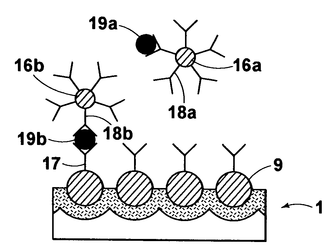
[0010]The primary object of the present invention is to provide a method of detecting a test body, wherein both the effect of a state, in which a fine metal particle on the side of a sensor chip and a fine metal particle on the side of the test body are located close to each other, and the effect of a state, in which fine metal particles having uniform size are arrayed regularly, are capable of being obtained.
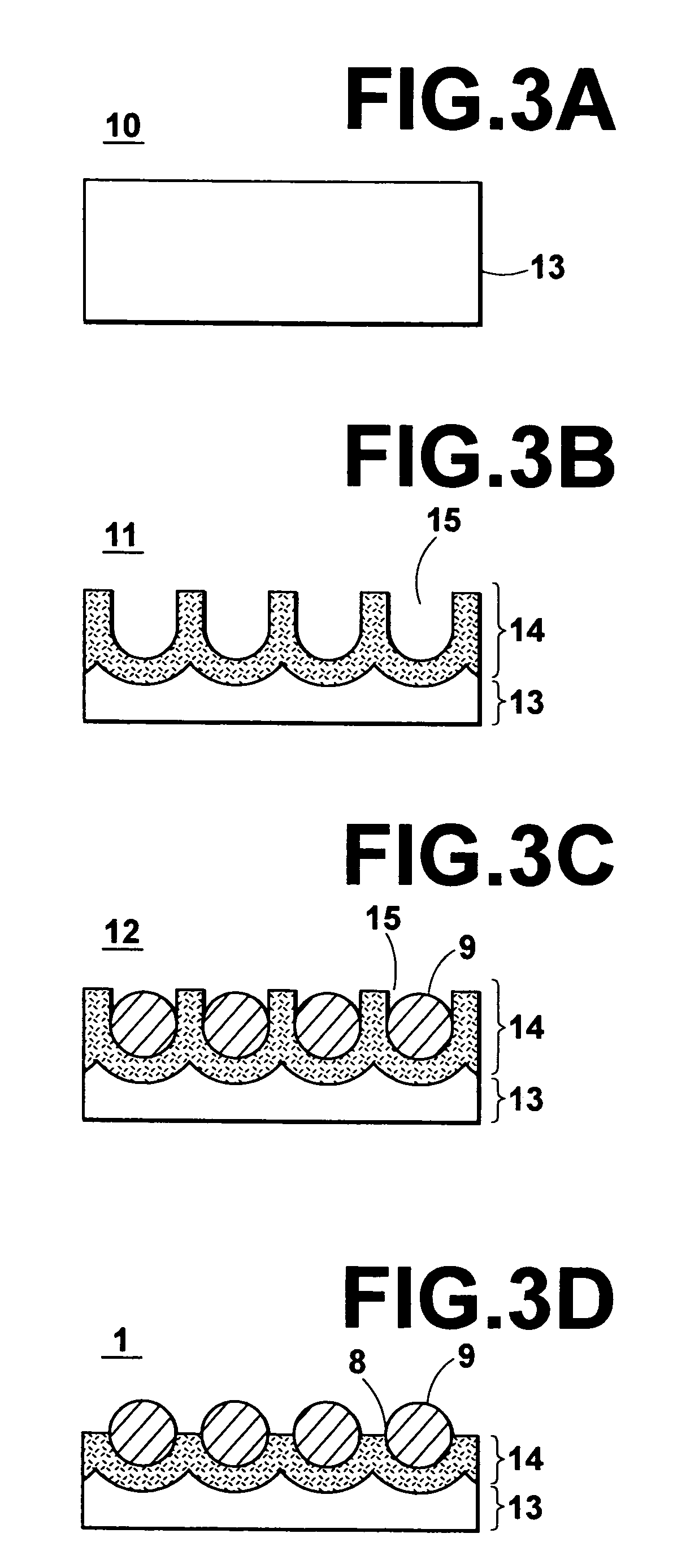
[0024]The method of detecting a test body in accordance with the present invention should preferably be modified such that the fine structure body comprises an alumina layer acting as the base body, which alumina layer has been formed with anodic oxidation of a material containing aluminum as a principal constituent, and the first fine metal particles, each of which is located in one of the fine holes of the alumina layer. The fine structure body having the structure described above is capable of being produced comparatively easily. Also, the fine structure body having the structure described above has little variation of the hole diameters of the fine holes and has a uniform surface structure. Therefore, with the fine structure body having the structure described above, reliable results are capable of being obtained from the measurement of the intensity of the light, which has been reflected from the surface of the fine structure body, or the light, which has passed through the fine structure body.
[0025]Also, the method of detecting a test body in accordance with the present invention should preferably be modified such that the fine structure body further comprises a thin metal film formed on areas of the surface of the base body, which areas are located around each of the fine holes of the base body. Further, the method of detecting a test body in accordance with the present invention should preferably be modified such that a diameter of each of the head regions of the first fine metal particles of the fine structure body is larger than the hole diameter of each of the fine holes of the fine structure body. With each of the aforesaid modifications of the method of detecting a test body in accordance with the present invention, the test body is capable of being detected with an enhanced sensitivity.
[0026]With the method of detecting a test body in accordance with the present invention, wherein the fine structure body having the uniform surface structure is employed, reliable measurement results are capable of being obtained. Also, in cases where the test body has been adsorbed to the surface of the fine structure body, the first fine metal particle and the second fine metal particle are capable of being located sufficiently close to each other, and the resonance wavelength of the localized plasmon resonance is capable of varying markedly. Therefore, the test body contained in the liquid is capable of being detected with a high sensitivity.
[0027]With the method of detecting a test body in accordance with the present invention, wherein the fine holes are formed with the anodic oxidation of the material containing aluminum as a principal constituent, the fine structure body having the uniform structure is capable of being obtained comparatively easily, and the sensing operation is capable of being performed with a high sensitivity.
[0028]The method of detecting a test body in accordance with the present invention may be modified such that the fine structure body further comprises the thin metal film formed on the areas of the surface of the base body, which areas are located around each of the fine holes of the base body. Further, the method of detecting a test body in accordance with the present invention may be modified such that the diameter of each of the head regions of the first fine metal particles of the fine structure body is larger than the hole diameter of each of the fine holes of the fine structure body. With each of the aforesaid modifications of the method of detecting a test body in accordance with the present invention, the sensitivity of the sensor is capable of being enhanced even further.

Problems solved by technology

With the sensor chip disclosed in Japanese Unexamined Patent Publication No. 2000-356587, the problems are encountered in that the colloidal particles are apt to agglomerate, and therefore the sensor chip is difficult to produce, and in that the sizes of the fine metal particles are not uniform.
However, with the fine structure body disclosed in Japanese Unexamined Patent Publication No. 2003-268592, wherein each of the fine metal particles is located in the interior of one of the fine holes, in cases where the technique for detecting a test body described in the aforesaid literature entitled “Metal Nanoparticles, Synthesis, Characterization, and Applications” is to be utilized, the problems are encountered in that it is difficult for a fine metal particle on the side of the sensor chip and a fine metal particle on the side of the test body to be located close to each other.

Method used


Image

  • Method of detecting test bodies
  • Method of detecting test bodies
  • Method of detecting test bodies

Examples


Embodiment Construction

[0037]The present invention will hereinbelow be described in further detail with reference to the accompanying drawings.

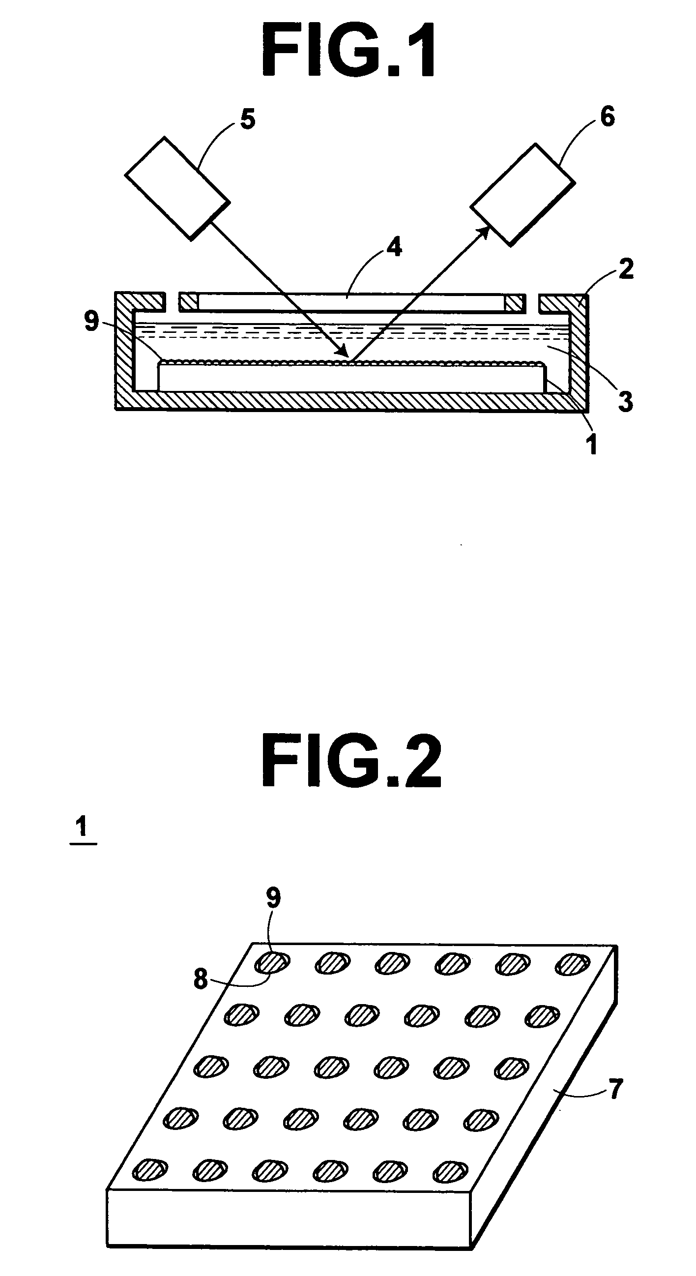
[0038]FIG. 1 is a schematic side view showing a reflection type of sensor, which is employed for detection of a test body in an embodiment of the method of detecting a test body in accordance with the present invention. As illustrated in FIG. 1, the sensor comprises a vessel 2 having a transparent window 4. The sensor also comprises a sensor chip 1, which is secured to the inside bottom surface of the vessel 2. The sensor further comprises a white light source 5 for irradiating white light 23 toward the sensor chip 1 having been secured to the inside bottom surface of the vessel 2. The sensor still further comprises a spectrophotometer 6 for spectrophotometrically detecting the light, which has been reflected from the surface of the sensor chip 1, and obtaining a spectrum of the reflected light. The spectrophotometer 6 thus detects a variation of the resonance wave...


PUM

PropertyMeasurementUnit
diameteraaaaaaaaaa
depthaaaaaaaaaa
hole diameteraaaaaaaaaa

Abstract

A fine structure body comprising first fine metal particles, which have head regions projected upwardly from a surface of a base body, is utilized. A substance capable of undergoing specific binding with a test body is fixed to the head regions of the first fine metal particles. Second fine metal particles, to which a substance capable of undergoing specific binding with the test body has been fixed, are dispersed in a sample liquid. The test body is detected from variation of a resonance wavelength of localized plasmon resonance, which variation occurs when the test body is adsorbed to the surface of the fine structure body by being sandwiched between the substance fixed to the first fine metal particle and the substance fixed to the second fine metal particle.

Description

BACKGROUND OF THE INVENTION[0001]1. Field of the Invention[0002]This invention relates to a method of detecting a test body with a sensor utilizing a localized plasmon resonance phenomenon.[0003]2. Description of the Related Art[0004]As sensors utilized for detection or identification of substances or for examination concerning molecular structures, sensors utilizing a localized plasmon resonance phenomenon have heretofore been known. The sensors utilizing the localized plasmon resonance phenomenon utilize a device having a structure, in which fine metal particles are secured in a layer-shaped form to a surface of a dielectric material, as a sensor chip. Also, the sensors are constituted of means for irradiating light to the layer of the fine metal particles of the sensor chip, and means for spectrophotometrically detecting the light, which has been reflected from the layer of the fine metal particles, and measuring the intensity of each of light components having different waveleng...

Claims


Application Information

Patent Timeline
Patent Type & Authority Patents(United States)
IPC IPC(8): G01N21/55G01N21/27B82Y15/00G01N21/41G01N33/543G01N33/553
CPCG01N21/554G01N33/54373G01N33/54346G01N2021/258
Inventor NAYA, MASAYUKI
Owner FUJIFILM HLDG CORP
Learn More