
Method and apparatus for detecting free fall

a technology of free fall detection and apparatus, applied in the field of data storage devices, can solve the problems of head to skip tracks, damage operating or unparked data storage devices, and onboard vehicular computers containing data storage devices such as hard disk drives, which are often dropped, bumped or bounced,

Inactive Publication Date: 2007-12-11
APPLE INC
View PDF55 Cites 22 Cited by
  • Summary
  • Abstract
  • Description
  • Claims
  • Application Information

AI Technical Summary

Benefits of technology

Effectively prevents data loss and head damage by parking the read / write head before impact, ensuring the data storage medium's safety during free fall and sudden acceleration changes, allowing for quicker response than existing technologies.

Problems solved by technology

Portable electronics devices such as digital and film cameras, notebook computers, and onboard vehicular computers containing data storage devices such as hard disk drives are often dropped, bumped, or bounced.
On earth, free fall usually immediately precedes an impact with a surface that may damage operating or unparked data storage devices, their spinning disks, actuators, and read / write heads.
Sudden acceleration or deceleration or excessive vibration of the disk drive can cause the head to skip tracks, to encode information incorrectly on the wrong track or tracks, to erase data previously encoded on the disk, or to dent the disk surface.
Thus, the more vibration experienced by the data processing system, the more the amplitude of the OTS increases.
Although the OTS system protects data stored on the data storage device from being erased or overwritten by the head, it does not prevent damage resulting from the head popping up and down onto the spinning disk when the data storage device is dropped and impacts a surface.
For example, if the head slams downward onto a spinning data medium device, such as a CD or DVD or magnetic hard disk, data may be irretrievably lost, the head may be severely damaged, and the CD, DVD, or magnetic hard disk may be irreparably dented.
Moreover, sensors found in the automobile field have not been used to protect data in data processing systems such as hard disk drives.
Unlike, the present invention, however, the buffering system does not protect the data storage device or its data actuating head from damage caused by dropping or vibrating the device.

Method used


Image

  • Method and apparatus for detecting free fall
  • Method and apparatus for detecting free fall
  • Method and apparatus for detecting free fall

Examples


Embodiment Construction

[0026]The acceleration sensor shown illustratively in the accompanying drawings is particularly suited to be of relatively small size for use in data processing systems used in notebook computer systems, digital cameras, music recording and playback devices, automobiles, marine vessels, aircraft, spacecraft, and similar equipment. Additionally, the embodiments of the present invention may be especially suited for use in a variety of additional applications not having data storage devices coupled to actuators and heads where it is desired to sense acceleration or detect a state of free fall. For example, this invention could be used to trigger inflation of a cushion to soften the impact for a dropped camera.

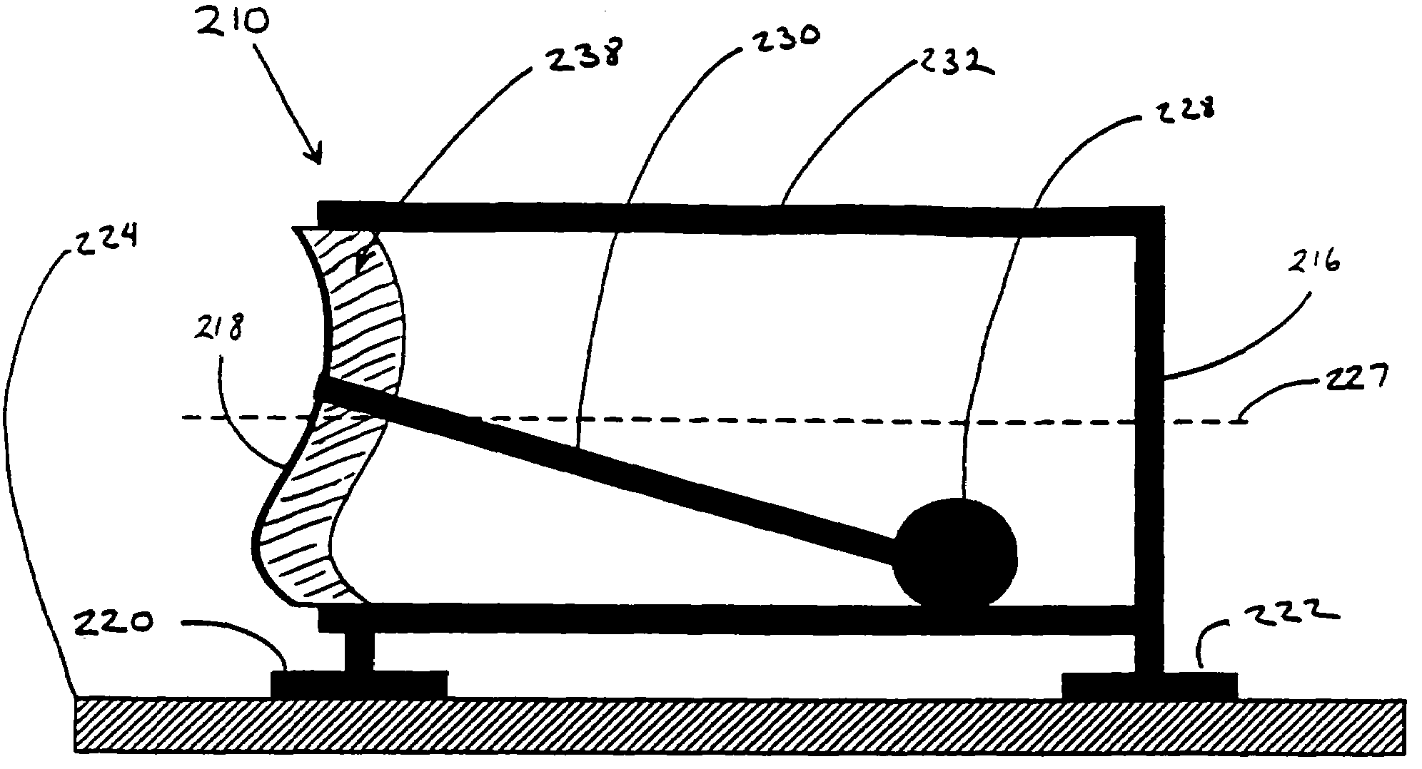
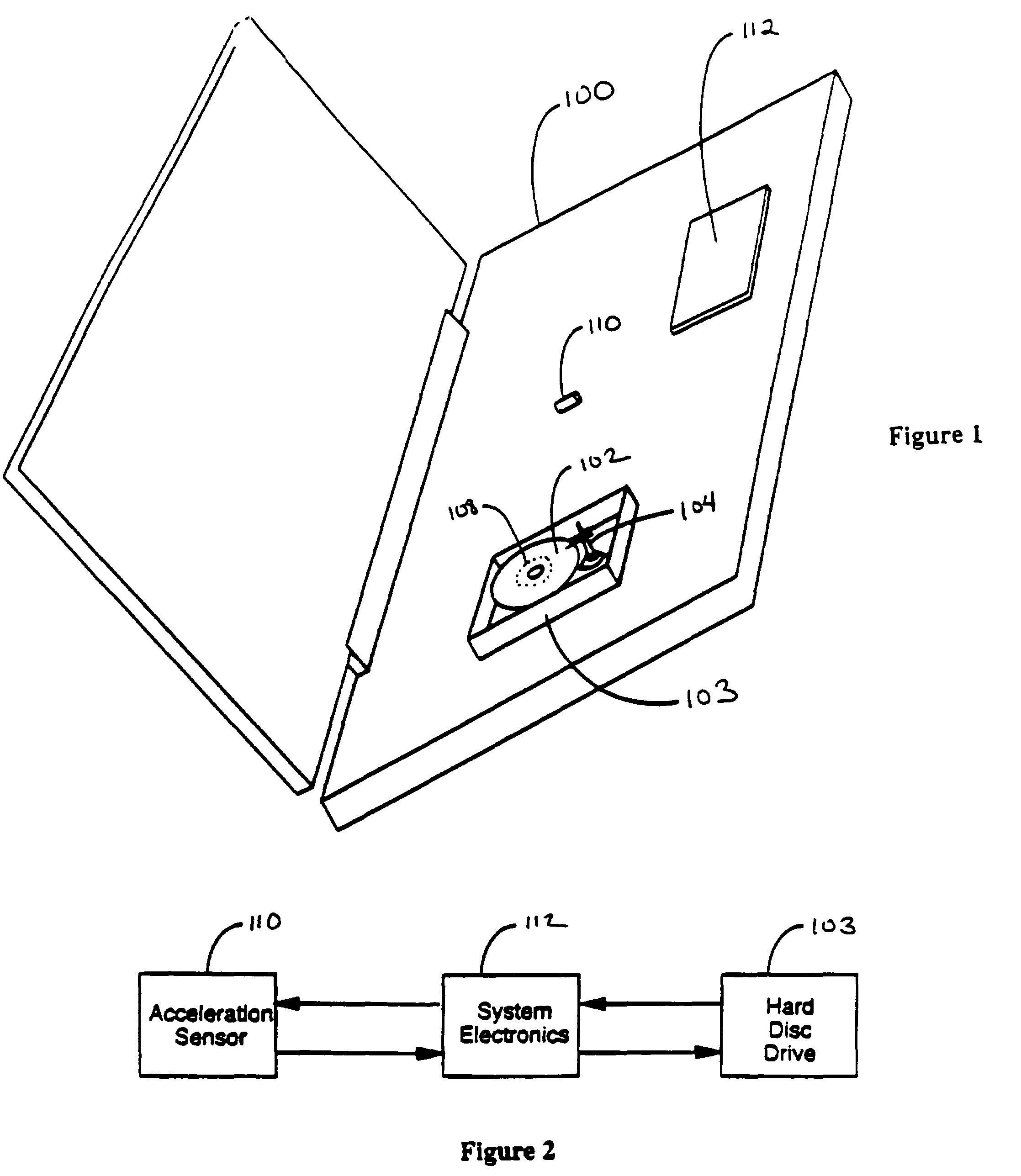
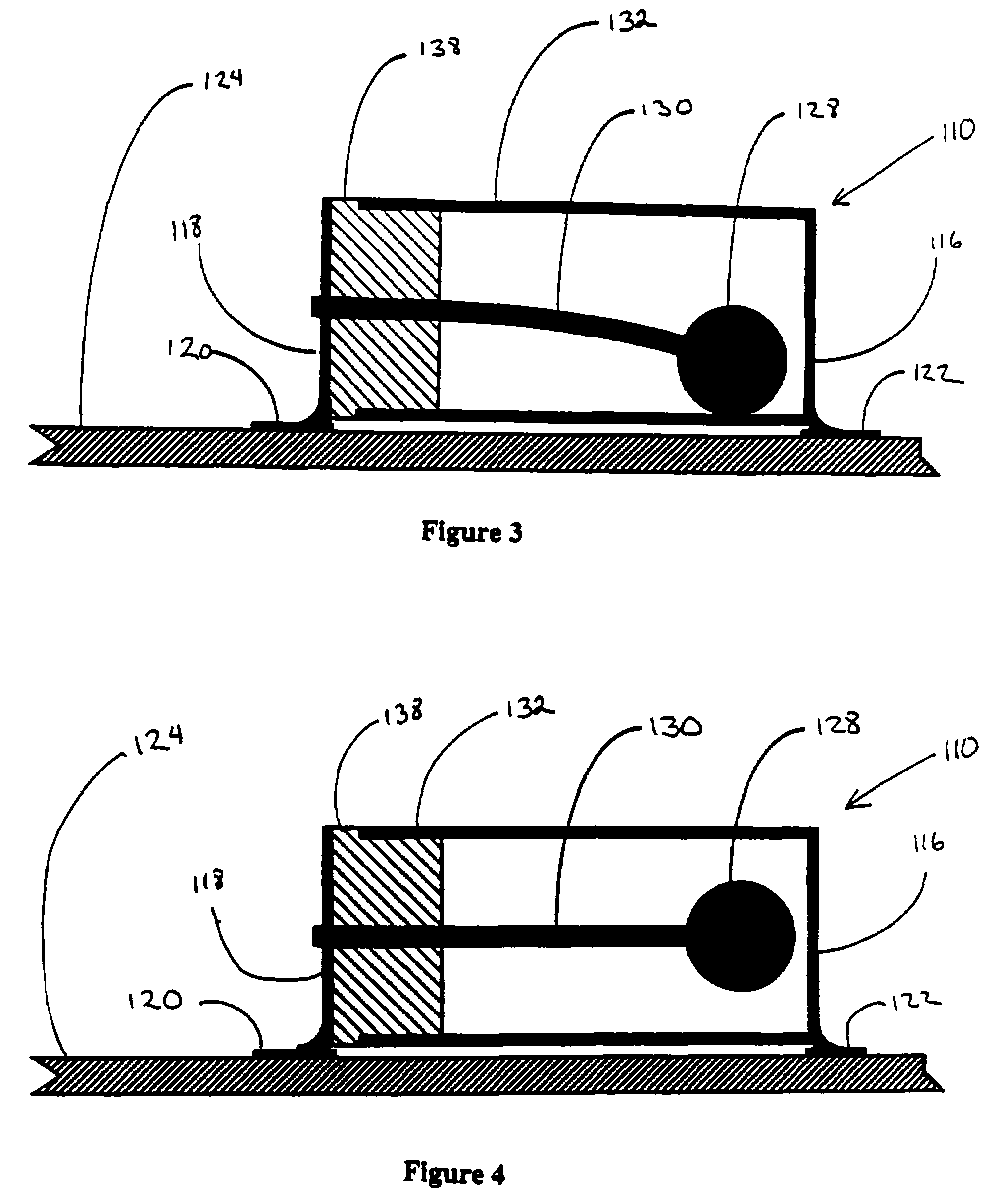
[0027]FIG. 1 shows a perspective view of a hard drive system. Typically, a data storage device 103, such as a hard disc drive system, is installed within a main housing of a computer 100, such as the notebook computer illustratively shown. However, it is understood that the invent...


PUM

PropertyMeasurementUnit
aspect ratioaaaaaaaaaa
timeaaaaaaaaaa
angleaaaaaaaaaa

Abstract

A data processing system including a data storage device having data stored on a data storage medium. Within said data processing system, a system electronics is operatively coupled to a sensor and to said data storage device. When the sensor senses a change in gravitational or inertial acceleration of said data processing system, it alerts system electronics to temporarily park a read / write head in a safe position.

Description

[0001]This application is a continuation application of U.S. patent application Ser. No. 10 / 348,465, filed on Jan. 21, 2003, now U.S. Pat. No. 6,768,006, which is a divisional application of U.S. patent application Ser. No. 09 / 678,541, filed on Oct. 2, 2000, now issued as U.S. Pat. No. 6,520,013.FIELD OF THE INVENTION[0002]This invention relates to data storage devices, such as hard disc drive assemblies and data processing systems, generally. In particular, the invention relates to data storage devices that are subject to free fall or other changes in acceleration, for example, storage devices used in portable computers, cameras, onboard vehicular computers, and similar electronic devices. ‘Free fall’ produces a change in the force, i.e. acceleration, of gravity as perceived in the frame of reference in which the data storage device is at rest.BACKGROUND[0003]Portable electronics devices such as digital and film cameras, notebook computers, and onboard vehicular computers containin...

Claims


Application Information

Patent Timeline
Patent Type & Authority Patents(United States)
IPC IPC(8): H01H35/14G06F9/46G11B19/04G11B19/08G11B21/12
CPCG11B19/04G11B21/12G11B19/08
Inventor WEHRENBERG, PAUL JAMES
Owner APPLE INC
Learn More