
Work light

a work light and light head technology, applied in the field of led work lights, can solve the problems of weakening the light head, affecting the light head, and compromising the strength of such two-piece light heads, and achieves the effects of high strength, easy impact resistance, and high strength

Inactive Publication Date: 2007-12-11
PANTHER VISION
View PDF29 Cites 10 Cited by
  • Summary
  • Abstract
  • Description
  • Claims
  • Application Information

AI Technical Summary

Benefits of technology

[0006]In accordance with the present invention, a light device is provided having an elongate body that has a high-strength construction. The high-strength light device is especially well-suited for use as a work light as its construction allows it to easily withstand impacts from hitting other hard objects, being dropped, or even run over by an automobile such as can occur when used around workshops, camp sites, and in auto repair facilities. The high strength body includes a handle at one end and a thin elongate light-transmissive portion including a tubular wall that extends from a larger diameter thereof at the handle to a smaller diameter at the other end of the body with a light source contained within an interior space defined by the tubular wall. It has been found that providing the tubular wall of the light transmissive portion with a taper along its length, and particularly along the inner surface thereof, allows the strength of the tubular wall to be optimized by molding the wall from a high strength material and so that it has an integral, one-piece construction.
[0007]Generally, prior work lights suggest use of high strength plastic material, but only with constant diameter, cylindrical light heads, which, in practice, require the light heads to have a two-piece construction that can compromise the strength, and particularly the pressure or compressive force resistance of such two-piece light heads. In contrast, the present light device takes advantage of the provision of a taper to the tubular, light-transmissive wall thereof which generally increases the strength of the wall as it progresses down to smaller and smaller diameters since there is more plastic material per unit area of space that the tubular wall encompasses. Moreover, the taper of the tubular wall permits it to be molded with a high-strength material and to have a one-piece, unitary, or integral construction.
[0008]It is believed that in practice the high-strength plastic or polymer material, for example, polycarbonate or acrylic plastic, typically has not been molded to form unitary cylindrical walls of the prior light heads because of material shrinkage during molding that makes it very difficult and unduly expensive to remove such a unitary cylindrical part from the mold. By contrast, the tapered, tubular wall of the light device herein allows for it to be molded as a single, unitary component even with high-strength plastic material that experiences significant dimensional shrinkage during molding so that it grips tightly onto part forming mold members. In this regard and as mentioned, it is the inner surface of the tubular wall that is tapered, whereas the outer wall surface may or may not include a taper, since it is the inner surface that is formed by a tapered core pin of the mold with the high-strength plastic material shrinking down and tightly gripping the pin. Nevertheless, by tapering the pin, it can more easily be pulled without having to utilize more complex and expensive molding equipment such as a collapsible core as may be necessitated where a constant diameter cylindrical wall is formed as with prior work light devices. Accordingly, as previously discussed, prior commercial work lights provided with a cylindrical, light-transmissive wall formed from two molded halves that are secured together along two-part lines generally will weaken the light head thereat absent additional fastening hardware that can unduly increase the size and expense thereof. In the present elongate, tapered light head, the light-transmissive tubular wall avoids these problems and provides the wall with its high-strength construction both because of its tapered configuration and by way of its one-piece, unitary construction utilizing high-strength plastic material therefor.
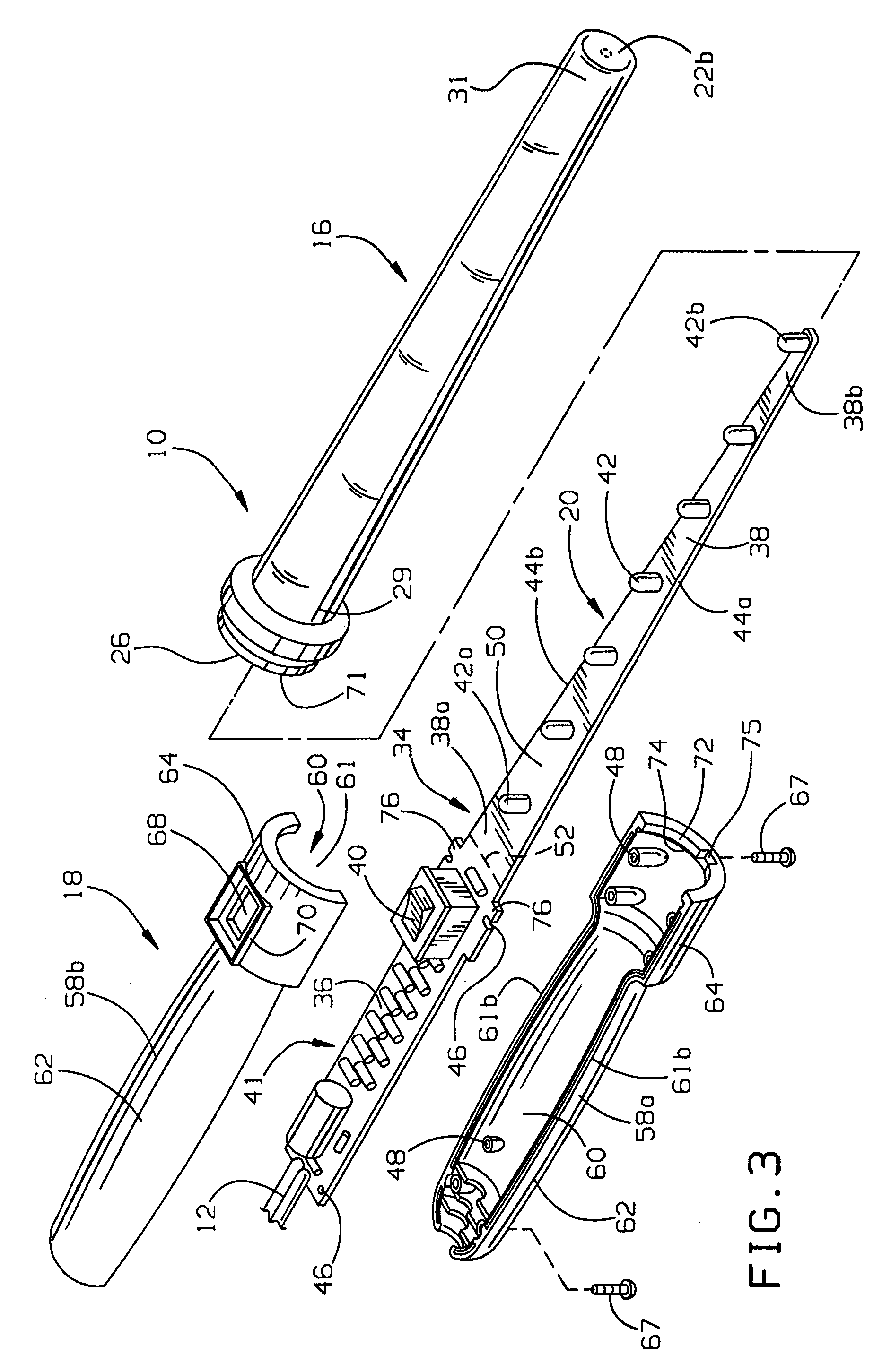
[0009]In one form, the light source includes a plurality of aligned LEDs. The use of small LEDs and their alignment is advantageous in keeping the diameters of the tapered, tubular wall to a minimum. In another form, the light source includes a printed circuit board that is inserted into an internal space defined by the tubular wall of the light-transmissive portion. Preferably, the printed circuit board has opposite sides that taper inward toward each other. In this configuration, the printed circuit board generally can have a wedge-type fit in the tapered, tubular wall of the light-transmissive body portion. Preferably, the printed circuit board is elongated and includes the plurality of LEDs aligned along one side of the printed circuit board.
[0012]In another form, the tubular wall diameters are optimized for both size and strength advantages. For instance, it is preferred to keep the size of the light-transmissive portion to a minimum for lighting of confined spaces. As a result, in a preferred embodiment, the tubular wall diameters do not exceed approximately 1 inch with an axial length of approximately 14.4 inches; however, longer or shorter light-transmissive portions may utilize larger or smaller diameters. At the same time, while the size is minimized, it is also preferred that the tubular wall have a configuration that is optimized for strength. To this end, the tubular wall may have a ratio of wall thickness to the cross-sectional area that it circumscribes including the internal space about which the wall extends that increases axially along the wall axis from the connection to the handle to the distal end portion. Therefore, such ratio allows the light-transmissive portion to be formed from the high-strength material as described above and, as a result, also have the desired high level of resistance to compressive pressure forces. In one form of the optimized construction, the wall thickness may be constant and the tubular wall may have side portions that taper inward toward each from the connection to the handle to the end portion.

Problems solved by technology

Generally, prior work lights suggest use of high strength plastic material, but only with constant diameter, cylindrical light heads, which, in practice, require the light heads to have a two-piece construction that can compromise the strength, and particularly the pressure or compressive force resistance of such two-piece light heads.
It is believed that in practice the high-strength plastic or polymer material, for example, polycarbonate or acrylic plastic, typically has not been molded to form unitary cylindrical walls of the prior light heads because of material shrinkage during molding that makes it very difficult and unduly expensive to remove such a unitary cylindrical part from the mold.
Accordingly, as previously discussed, prior commercial work lights provided with a cylindrical, light-transmissive wall formed from two molded halves that are secured together along two-part lines generally will weaken the light head thereat absent additional fastening hardware that can unduly increase the size and expense thereof.

Method used


Image

  • Work light
  • Work light
  • Work light

Examples


Embodiment Construction

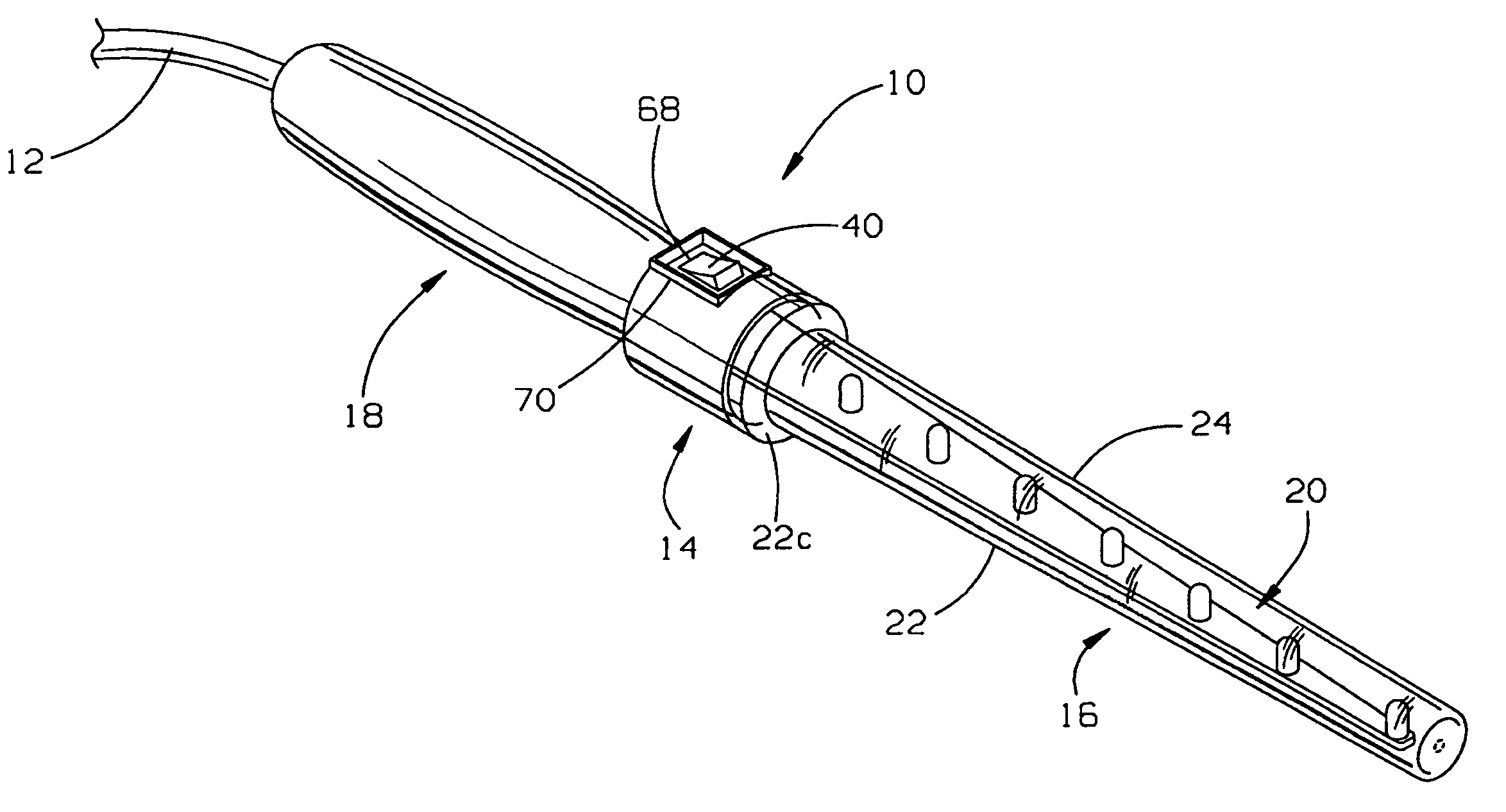
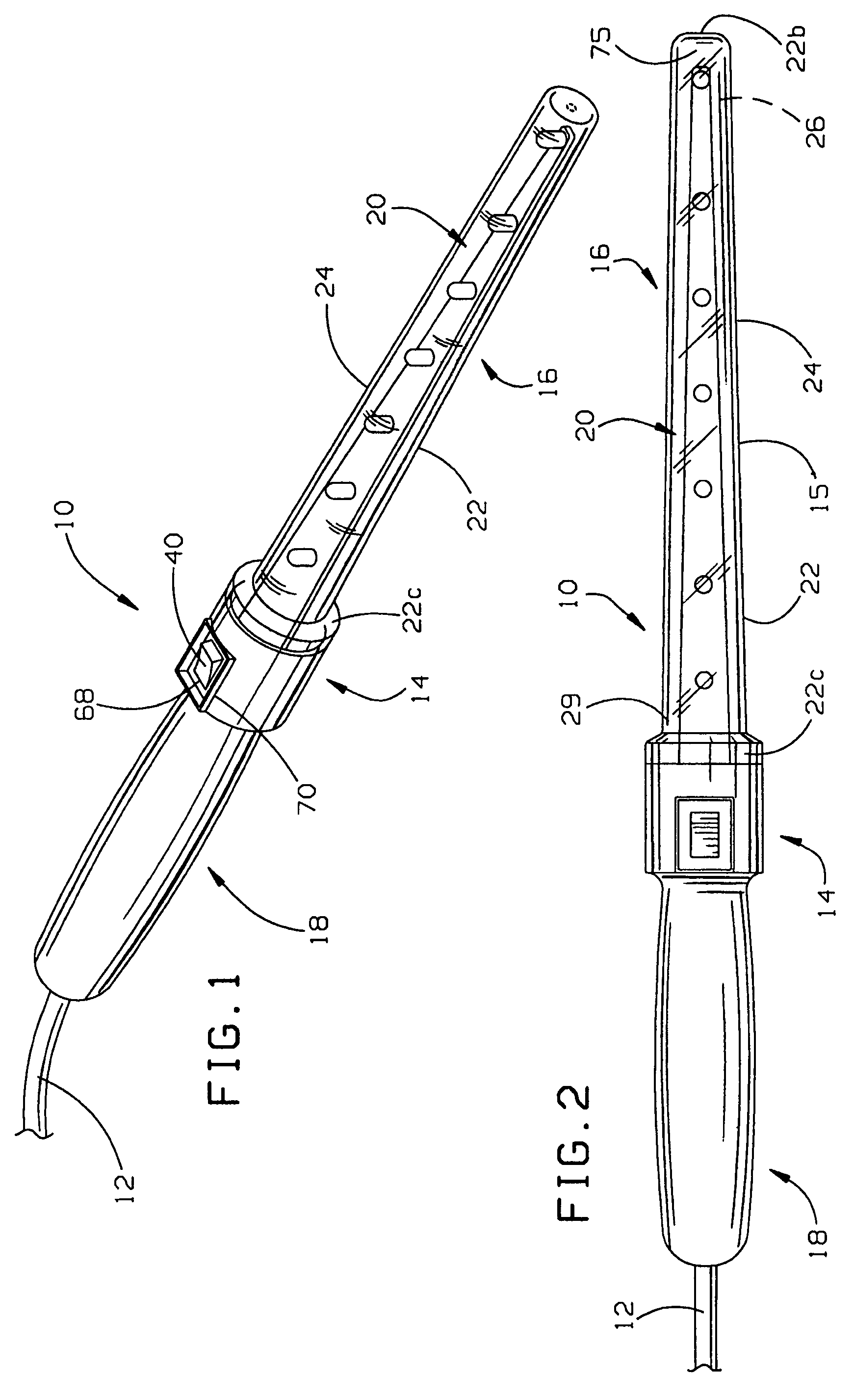
[0039]In FIGS. 1 and 2, an LED work light 10 is shown that is provided with a high-strength construction in accordance with the present invention. The light 10 may be powered from a standard 110 volt wall outlet through a cord 12 plugged into the outlet in a known manner. Battery powered and combination units providing options in terms of powering the light device with either power from a wall outlet or a battery are also contemplated. The batteries can be rechargeable. Further, the cord 12 can be provided with a connector that allows it to be plugged into a typical cigarette lighter in a vehicle to be powered by the electrical power source thereof. In this regard, the power cord 12 can be provided in different lengths on different light units 10 such as with a twenty foot length for automobiles or a forty foot length for trucks.

[0040]In general, the light 10 includes a high-strength, elongate body 14 including an elongate, light head 15 having a substantially light-transmissive por...


PUM


Abstract

A light device is provided having an elongate body that has a high strength construction. The high-strength light device is especially well-suited for use as a work light. The work light includes a high-strength body that has a handle and an elongate light-transmissive portion extending from the handle. Preferably, the light-transmissive portion includes a one-piece tubular wall that is tapered and which is molded from a high-strength material.

Description

FIELD OF THE INVENTION[0001]The invention is directed to a lighting device and, more particularly, to a LED work light.BACKGROUND OF THE INVENTION[0002]Work lights or shop lights are useful lighting devices having wide applications for providing illumination in rugged environments such as workshops, garages, campsites, and many other places. Given the rugged environment in which the lights are used in, it is generally required that the work light have a robust construction such that the light source is not damaged or broken during use.[0003]Common work lights use a variety of different lighting sources to provide illumination. For instance, incandescent or fluorescent light bulbs are common lighting sources used in the work light. While such bulbs are capable of providing sufficient illumination, they have the shortcoming of being fragile and, therefore, requiring relatively large or bulky housings to protect the bulbs from breakage. For instance, incandescent light bulbs, such as a...

Claims


Application Information

Patent Timeline
Patent Type & Authority Patents(United States)
IPC IPC(8): F21S4/00
CPCF21L4/00F21L14/023F21V21/08F21V31/005F21Y2103/003F21V23/005F21Y2101/02F21Y2103/10F21Y2115/10
Inventor WATERS, MICHAEL
Owner PANTHER VISION
Learn More