
Control apparatus for an internal combustion engine

a control apparatus and internal combustion engine technology, applied in the direction of electric control, combustion air/fuel air treatment, instruments, etc., can solve the problems of affecting the efficiency of combustion engines

Active Publication Date: 2007-12-11
MITSUBISHI ELECTRIC CORP
View PDF5 Cites 52 Cited by
  • Summary
  • Abstract
  • Description
  • Claims
  • Application Information

AI Technical Summary

Benefits of technology

[0014]According to the present invention, a deviation in the relation between the effective opening area and the throttle opening is learned and corrected on the basis of a deviation between the target amount of intake air and the actual amount of intake air, so even in case where there are variations in the throttle body and the various kinds of sensors or various estimation errors, the throttle opening can be controlled so as to make the amount of intake air coincide with the target amount of intake air in an accurate manner.

Problems solved by technology

As a result, it is difficult to accurately set the flow coefficient in a state in which the degree of opening and an effective opening area of the throttle valve are not decided.
That is, the target throttle effective opening area to obtain the target amount of intake air can not be calculated accurately, so there arises a deviation between the target amount of intake air and the actual amount of intake air, and besides a lot of labor is required to obtain the flow coefficient and to set a map therefor.
In this case, however, there is the following problem.
Further, there takes place a variation in the calculated effective opening area due to the variation and / or estimation error of various kinds of sensors that measure the intake manifold pressure, the atmospheric pressure, the intake air temperature, etc.
As a result, there is a problem that there arises a variation in the actual amount of intake air with respect to the target amount of intake air due to the variation of the throttle body and the various kinds of sensors, various kinds of estimation errors, etc.

Method used


Image

  • Control apparatus for an internal combustion engine
  • Control apparatus for an internal combustion engine
  • Control apparatus for an internal combustion engine

Examples


embodiment 1

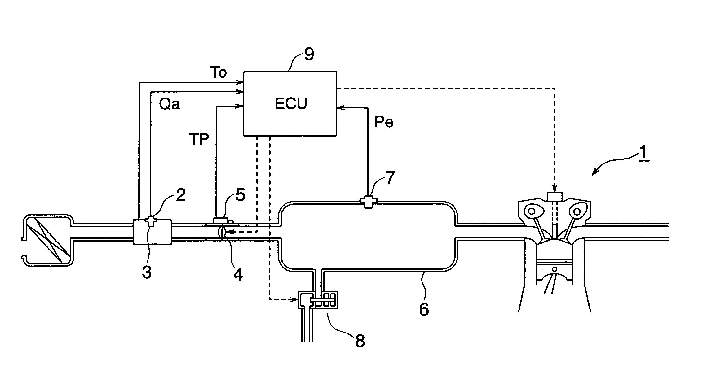
[0026]Referring to the accompanying drawings and first to FIG. 1, therein is conceptually shown the construction of a control apparatus for an internal combustion engine according to a first embodiment of the present invention, and FIG. 2 is a block diagram that shows the schematic configuration of an engine control part of the control apparatus for an internal combustion engine according to the first embodiment of the present invention.

[0027]In FIG. 1, at an upstream side of an intake passage that constitutes an intake system of an engine 1, there are arranged an air flow sensor 2 that measures the flow rate of intake air Qa sucked to the engine 1 (hereinafter referred to as “the amount of intake air”), and an intake air temperature sensor 3 that measures the temperature of intake air To (hereinafter referred to as “the intake air temperature”).

[0028]Here, note that the intake air temperature sensor 3 may be formed integrally with the air flow sensor 2, or may be formed separately ...

embodiment 2

[0110]Though not particularly referred to in the above-mentioned first embodiment, for example as shown in FIG. 6, in case where the CAt-TP map (see a broken line) crosses with respect to the actual CAt-TP relation (see a solid line), or an error of the CAt-TP map (see an alternate long and short dash line) with respect to the actual CAt-TP relation is not constant (parallel), there is a possibility that problems such as a follow-up delay, an overshoot, etc., might occur at the time of a transient operation if the throttle opening learning value TPLRN is used independently.

[0111]Accordingly, in order to deal with the case where the CAt-TP maps (see the broken line and the alternate long and short dash line) are not constant with respect to the actual CAt-TP relation (solid line) (see FIG. 6), it is desirable that as shown in FIG. 7, provision be made for a throttle opening learning value distribution section 24 that is arranged downstream of the throttle opening learning value calcu...


PUM


Abstract

In throttle control, a throttle opening is set with sufficient control accuracy in accordance with the operating state of an engine despite variations in a throttle body and various kinds of sensors. A target effective opening area is calculated from a target amount of intake air, an atmospheric pressure, an intake pipe internal pressure and an intake air temperature by using a flow rate formula for a throttle type flow meter. A target throttle opening is calculated from a correlation map. An actual effective opening area is calculated from the amount of intake air, the atmospheric pressure, the intake pipe internal pressure, and the intake air temperature by using the above-mentioned flow rate formula, and a learning throttle opening is calculated from the correlation map. The target throttle opening is corrected by a throttle opening learning value calculated from a deviation between the target throttle opening and the learning throttle opening.

Description

BACKGROUND OF THE INVENTION[0001]1. Field of the Invention[0002]The present invention relates to a control apparatus for an internal combustion engine capable of controlling the opening of a throttle valve so as to obtain a target amount of intake air.[0003]2. Description of the Related Art[0004]In recent years, there has been proposed a control apparatus for an internal combustion engine that can obtain excellent driving performance by using, as a requested value of a driving force from a driver or a vehicle side, the output shaft torque of the internal combustion engine (hereinafter also referred to simply as an engine) which is a physical quantity directly acting on the control of the vehicle, and by deciding, as an output target value of the engine in the form of the output shaft torque, engine control quantities in the form of an amount of air, an amount of fuel and ignition timing.[0005]In addition, it is generally known that a control quantity having the greatest influence on...

Claims


Application Information

Patent Timeline
Patent Type & Authority Patents(United States)
IPC IPC(8): F02D9/08B60T7/12
CPCF02D9/02F02D41/0002F02D41/18F02D41/2464F02M35/10052F02M35/10295F02M35/1038F02M35/10386F02D11/105Y02T10/42F02D41/2448F02D2200/0404F02D2200/0406F02D2200/0414F02D2200/703Y02T10/40
Inventor HAGARI, HIDEKINISHIMURA, HIDEKI
Owner MITSUBISHI ELECTRIC CORP
Learn More