
Method for control of dilution in engines during variable camshaft phasing

a variable camshaft and phasing technology, applied in the direction of electric control, machines/engines, output power, etc., can solve the problems of excessive dilution or suboptimal dilution, too much dilution, too little dilution when load is decreasing,

Active Publication Date: 2007-12-11
DELPHI TECH IP LTD
View PDF1 Cites 11 Cited by
  • Summary
  • Abstract
  • Description
  • Claims
  • Application Information

AI Technical Summary

Benefits of technology

This approach ensures optimal fuel mixture dilution during transient engine operation, improving fuel economy and reducing NOx emissions by precisely coordinating phaser and throttle responses to engine load changes.

Problems solved by technology

A problem arises, however, during transient periods between different engine states of speed and load requiring movement of each phaser from a first position to a second position, during which time it is necessary to carefully coordinate phaser positions to the load response of the engine.
Depending on the response rate of the cam phasers relative to the load response of the engine, periods of either excessive dilution or sub-optimal dilution can result.
If phaser response is relatively fast, the result will be too much dilution when engine load is increasing, and too little dilution when load is decreasing.
Excessive dilution causes unstable combustion, while sub-optimal dilution reduces fuel economy and increases NOx emissions.

Method used


Image

  • Method for control of dilution in engines during variable camshaft phasing
  • Method for control of dilution in engines during variable camshaft phasing
  • Method for control of dilution in engines during variable camshaft phasing

Examples


Embodiment Construction

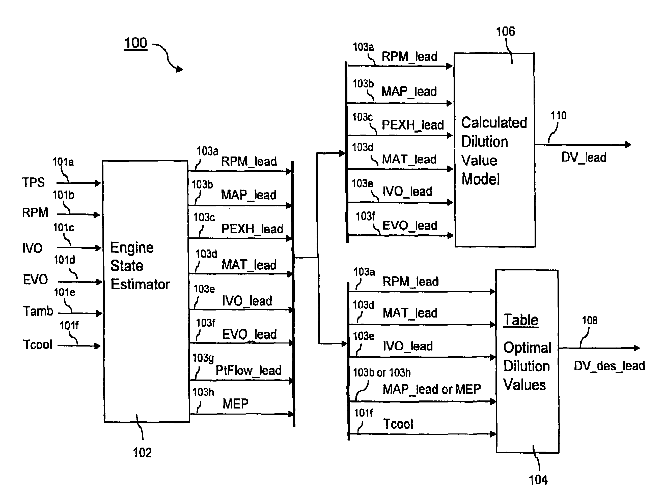
[0018]Referring to FIG. 1, a throttle and cam phaser control system 10 for use in accordance with the invention comprises an internal combustion engine 12 having an intake manifold 14 for supplying intake air to engine 12 and a throttle valve 16 for regulating the flow of air into manifold 14. The position of throttle valve 16 is regulated by a signal 18 sent from an electronic throttle controller (ETC) 20.

[0019]Engine 12 includes at least an intake valve camshaft phaser 22, or an exhaust valve camshaft phaser 24 and optionally both an intake and exhaust valve camshaft phaser 22,24. Each phaser 22,24 sends a position signal 26,28 to an engine control module (ECM) 30 defining a programmable controller or computer as is known in the engine control arts; and each phaser 22,24 receives a position command 32,34 from ECM 30. (For engines not equipped with an exhaust valve camshaft phaser 24, signals 28,34 obviously are omitted. For engines not equipped with an intake valve camshaft phaser...


PUM


Abstract

A method for coordinating engine throttle position with camshaft phaser motion during transient engine operation such that desired internal residual dilution is maintained. A dilution model for residual mass fraction and a table of desired dilution values are embedded in the engine control algorithm. The dilution model is applied to calculate the desired throttle and camshaft phaser positions for the next intake event. In a first method, if the throttle is capable of changing the airflow into the engine cylinders faster than the camshaft phasers can respond, the throttle is modulated to maintain desired dilution levels while the phasers are allowed to move as fast as they can. In a second method, if the phaser response faster than the engine intake port airflow response to a throttle position change, the throttle is allowed to move as fast as it can while phaser motion is modulated to maintain desired dilution levels.

Description

TECHNICAL FIELD[0001]The present invention relates to internal combustion engines; more particularly, to such engines having capabilities for variable camshaft phasing; and most particularly, to a method for controlling fuel mixture dilution during speed and load transients in such engines.BACKGROUND OF THE INVENTION[0002]Internal combustion engines having variable camshaft phasing are well known. Camshaft phasers are used to improve fuel economy and reduce formation of nitrogen oxides (NOx) by adjusting the timing of Intake Valve Opening (IVO), Exhaust Valve Closing (EVC), or both IVO and EVC independently so that the engine cylinders are held at their dilution limit during operating conditions of partial load. Cylinder dilution is defined as the fraction of burned gas left over from the previous combustion event that is contained in the cylinder during the compression stroke.[0003]Under steady state operating conditions, the optimum positions of the cam phaser or cam phasers as a ...

Claims


Application Information

Patent Timeline
Patent Type & Authority Patents(United States)
IPC IPC(8): F01L1/34
CPCF01L1/34F02D13/0219F02D41/18F02D41/0002F01L2800/00F02D11/105Y02T10/18F02D2041/002F02D2200/0402Y02T10/42Y02T10/12Y02T10/40
Inventor SINNAMON, JAMES F.
Owner DELPHI TECH IP LTD
Learn More