
Lean-staged pyrospin combustor

a pyrospin and combustor technology, applied in the field of combustor, can solve the problem of not exactly equal fuel-air ratio, and achieve the effects of increasing the power output of the engine, reducing nitrous oxide emissions, and increasing power

Active Publication Date: 2007-12-04
HAMILTON SUNDSTRAND CORP
View PDF8 Cites 97 Cited by
  • Summary
  • Abstract
  • Description
  • Claims
  • Application Information

AI Technical Summary

Benefits of technology

[0007]Fuel is introduced into the intermediate zone of the combustion chamber by a second plurality of injectors. The second plurality of injectors includes an orifice that is directed to introduce fuel into the intermediate zone. The fuel-air mixture introduced into the primary and intermediate zones are essentially the same to provide a consistent lean fuel-air mixture. The additional quantity of fuel-air mixture into the combustor increases the power output of the engine. The additional fuel-air mixture in the intermediate zone at the same fuel-air ratio as is introduced in the primary zone and provides for the increase of power without increasing the fuel-air ratio or temperature within the combustor.
[0008]Accordingly, the combustor of this invention provides for optimal operation of a gas turbine engine during starting conditions and during engine load operating conditions without an increase in temperature to therefore reduce nitrous oxide emissions.

Problems solved by technology

However, each of these devices requires a compromise of the two desirable conditions.
That is, during the starting condition the fuel-air ratio is not exactly as would otherwise be desired because of the performance requirements required of the gas turbine engine under full load conditions.

Method used


Image

  • Lean-staged pyrospin combustor
  • Lean-staged pyrospin combustor
  • Lean-staged pyrospin combustor

Examples


Embodiment Construction

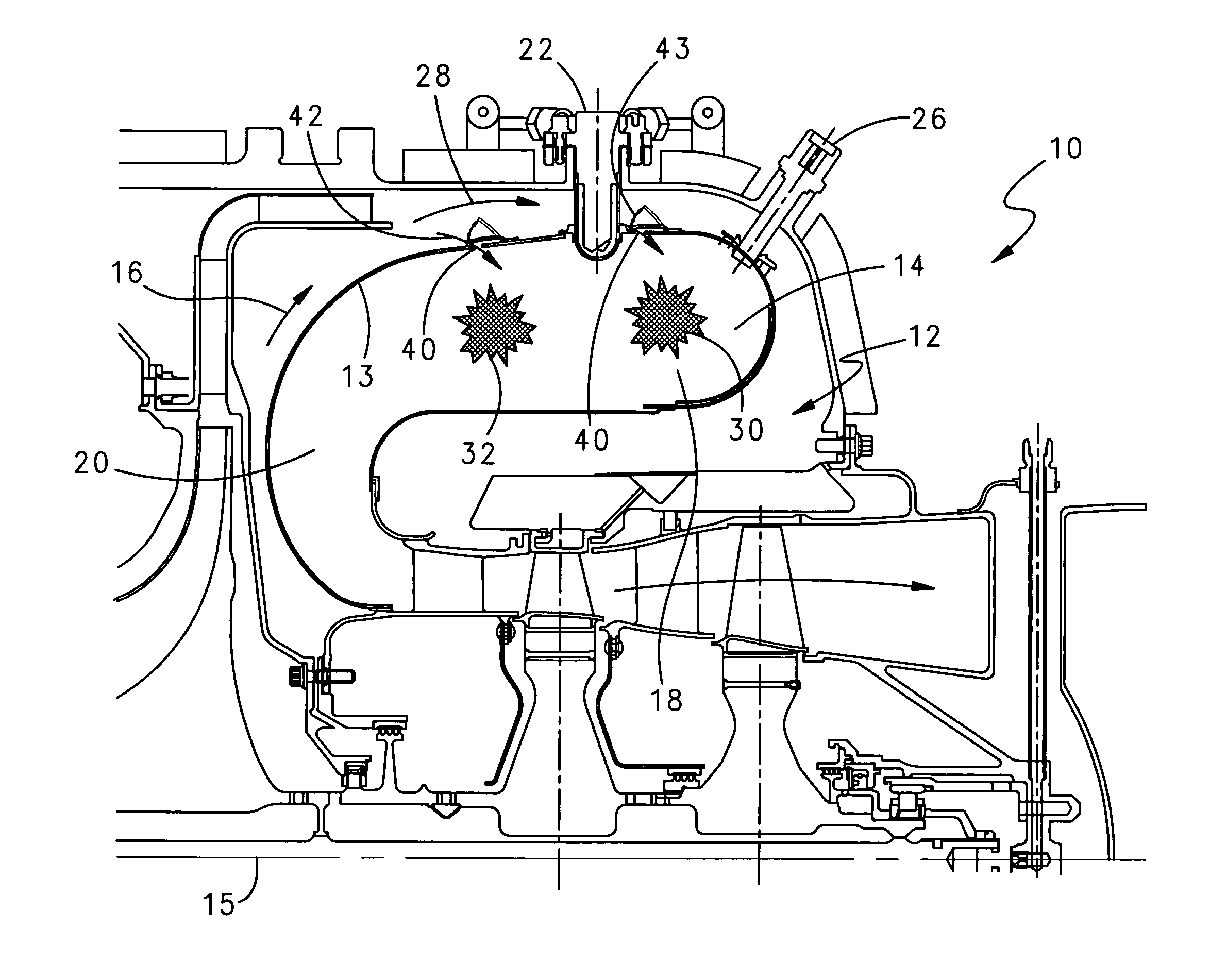
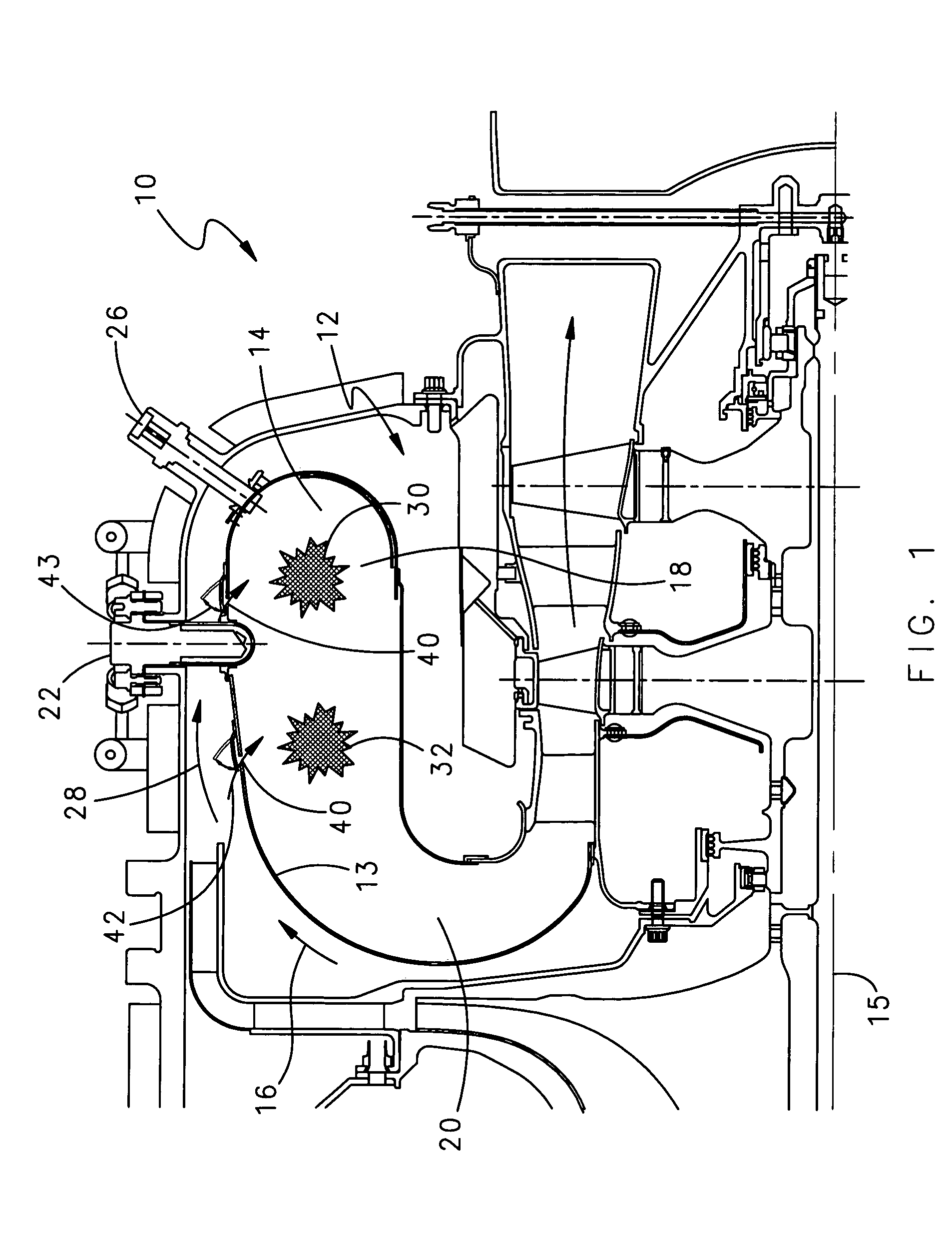
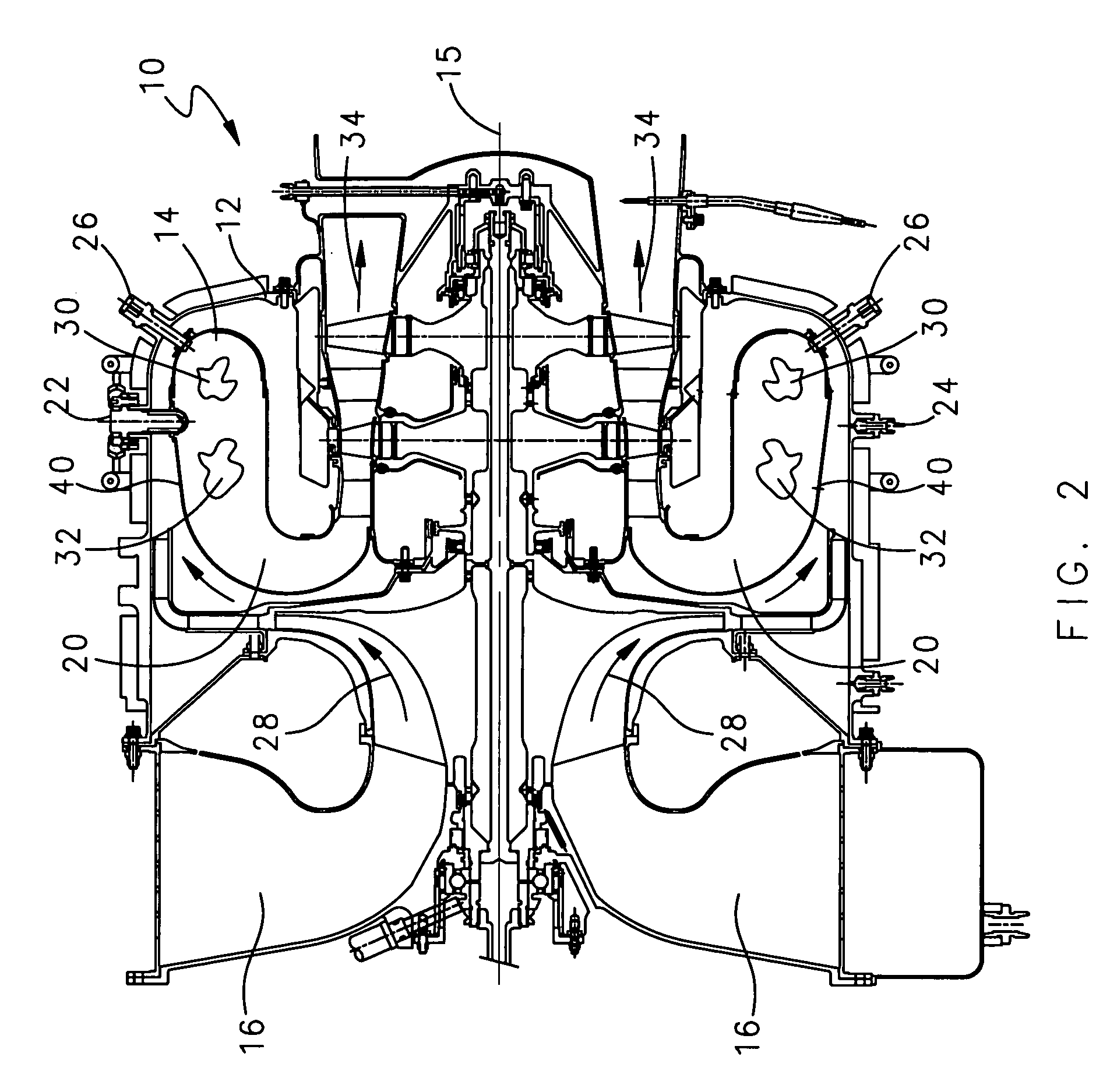
[0014]Referring to FIG. 1, a gas turbine engine assembly 10 includes a combustor 12 that includes a combustor chamber 14. The combustor chamber 14 includes an interior portion 18 and an outlet portion 20. Within the interior portion 18 is a primary zone 30. Adjacent the outlet portion 20 is an intermediate zone 32. The combustor chamber 14 illustrated is of a reverse annular configuration. A worker with the benefit of this disclosure would understand the application of this invention to combustors of other designs and configurations.

[0015]The combustor 12 includes a first plurality of injectors 22. The combustor 12 further includes a second plurality of injectors 24 (Best shown in FIG. 3). Each of the first and second pluralities of injectors 22, 24 are disposed in the combustor 12 at a position adjacent both the primary and intermediate zones 30, 32.

[0016]The combustor 12 also includes a plurality of effusion openings 40 that communicate high-pressure air into the combustor chamber...


PUM


Abstract

A combustor assembly includes a combustor chamber having a primary and intermediate zone that provides for reduced flame temperatures. The combustor assembly includes first and second pluralities of injectors. The first plurality of injectors introduces fuel to a primary zone. A second plurality of injectors introduces fuel to an intermediate zone. During operation between initial start up and before the introduction of engine load, fuel is introduced into the primary zone only by the first plurality of injectors. Once engine load is applied to the engine, fuel is introduced into the intermediate zone by the second plurality of injectors. Introduction of additional volume of fuel allows the fuel-air ratio to remain constant regardless of engine operating conditions. The constant fuel-air ratio is maintained at a desired rate to lower flame temperatures and reduce nitrous oxide emissions.

Description

BACKGROUND OF THE INVENTION[0001]This invention relates generally to a combustor and specifically to a combustor including features reducing nitrous oxide (NOx) emissions.[0002]Conventional gas turbine engines include a combustor for mixing and burning a fuel air mixture to produce an exhaust gas stream that turns a turbine. Conventional combustors operate near stoichiometric conditions in the primary zone. Such conditions produce higher than desired combustor temperatures. The high combustor temperatures produce greater than desired amounts of nitrous oxide. Environmental concerns and regulation have created the demand for gas turbine engines with reduced nitrous oxide emissions.[0003]Current combustors utilize many different configurations to optimize burning of fuel within the combustor. Many of these configurations include devices for initiating swirl of the fuel and air mixture within the combustor. Such devices improve the efficiency of fuel burning within the combustor. Howev...

Claims


Application Information

Patent Timeline
Patent Type & Authority Patents(United States)
IPC IPC(8): F23R3/34F23R3/54
CPCF23R3/54F23R3/34F23D2900/00014
Inventor CHEN, DAIH-YEOU
Owner HAMILTON SUNDSTRAND CORP
Learn More