
Liquid-crystal display apparatus capable of reducing line crawling

Inactive Publication Date: 2007-11-27
ONANOVICH GROUP
View PDF9 Cites 14 Cited by
  • Summary
  • Abstract
  • Description
  • Claims
  • Application Information

AI Technical Summary

Benefits of technology

[0016]The present invention has been made to solve the foregoing issues. It is an object of the present invention to provide a liquid-crystal display apparatus having a good image quality by making use of a plural-fold scanning line method and by substantially reducing line crawling. Further, it is another object of the present invention to provide a liquid-crystal display apparatus having the above qualities and which is capable of reducing power consumption.

Problems solved by technology

However, source drivers consume more power and are more expensive than the gate drivers.
There are some drawbacks, however, of using 3:1 interlaced driving methods.
The use of common inversion driving, however, can be problematic in some cases when it is employed in conjunction with 3:1 interlaced driving and tripled-scanning-line-methods.
For example, problems can occur if the distance D between a plurality of lines obtained when dots having the same basic color and being driven by the same-polarity driving voltage are connected to each other in their vicinities is 6P (where P indicates the pitch of color pixels each formed of three dots).
Conversely, to set the line distance D to 260 μm or shorter, the color pixel pitch needs to be 43 μm or less, which is currently difficult to produce in the making of high-pixel-density display units.
In other words, when common inversion driving is employed together with the conventional tripled-scanning line method, it is difficult to apply a sufficient countermeasure to line crawling.
Therefore, power consumption increases since the power consumption of using only source drivers is about four times as large as in common inversion driving.

Method used


Image

  • Liquid-crystal display apparatus capable of reducing line crawling
  • Liquid-crystal display apparatus capable of reducing line crawling
  • Liquid-crystal display apparatus capable of reducing line crawling

Examples


first embodiment

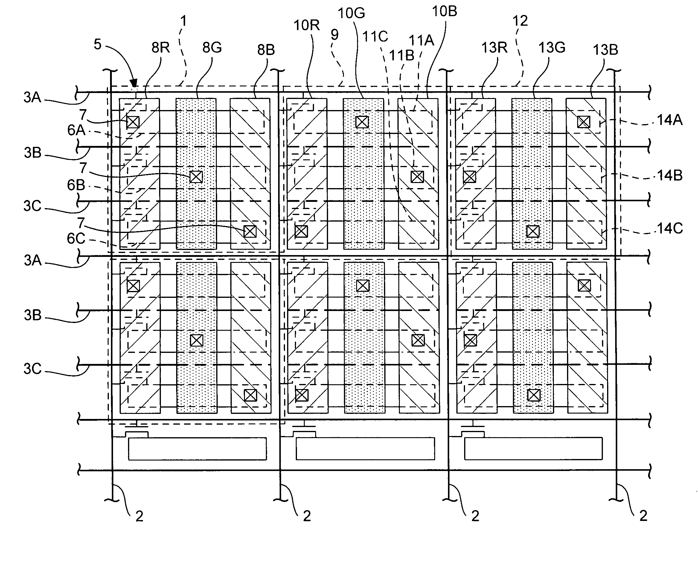
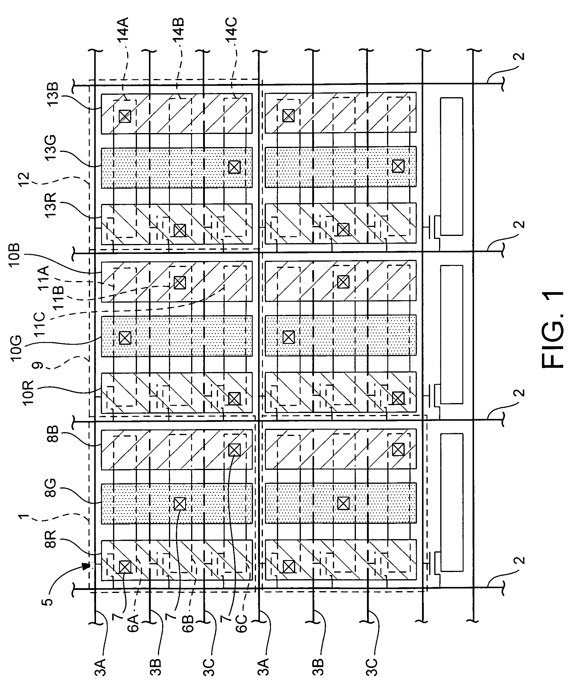
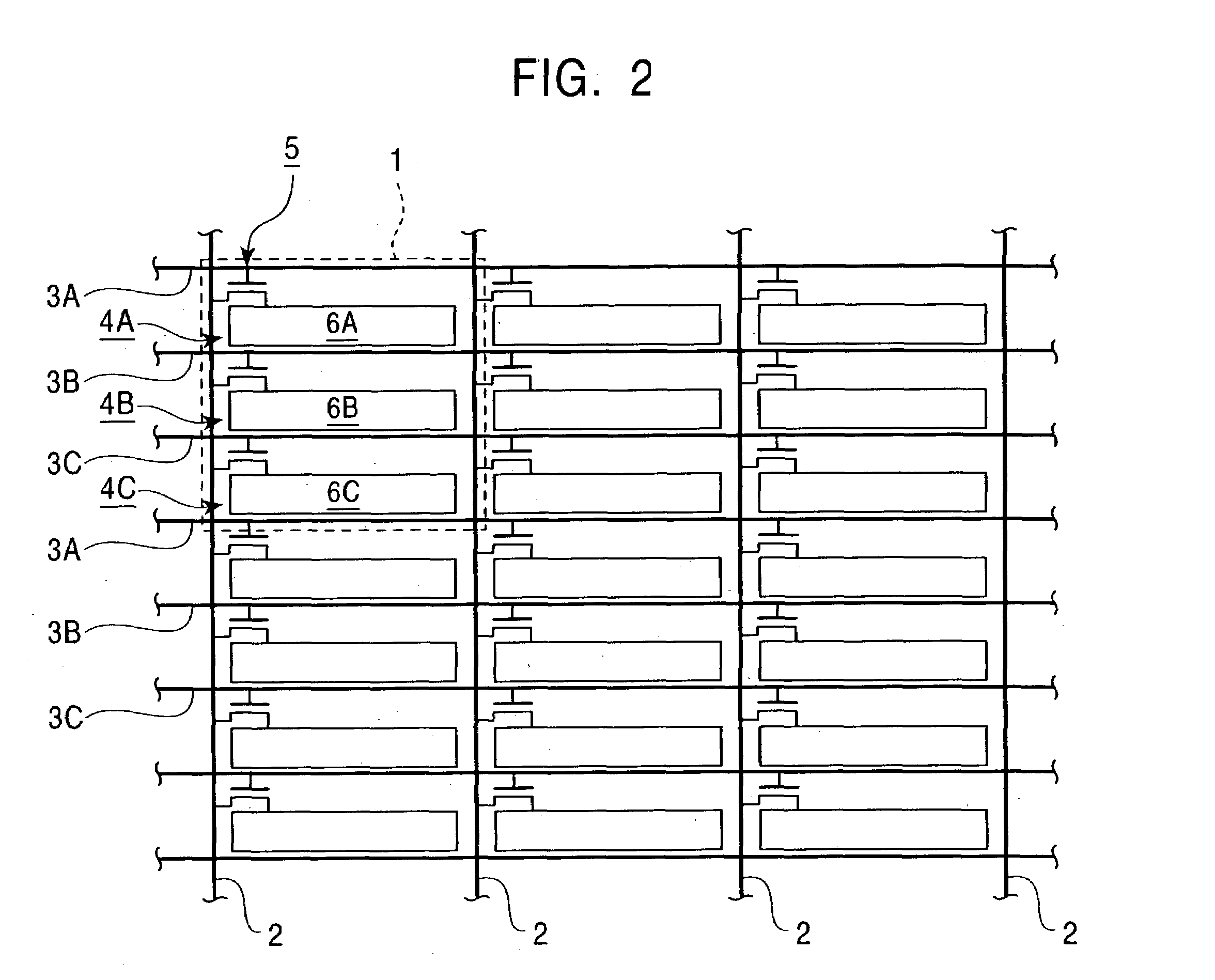
[0092]A liquid-crystal display apparatus according to a first embodiment of the present invention will be described below by referring to FIG. 1 to FIG. 4.

[0093]The liquid-crystal display apparatus of the present embodiment is an active-matrix liquid-crystal display apparatus in which liquid crystal is sandwiched by an active-matrix-substrate and an opposing substrate disposed oppositely. On the active-matrix substrate, a plurality of signal lines and a plurality of scanning lines are provided in a checker-pattern manner, and a great number of color pixels each having three basic colors, R, G, and B are provided in a matrix manner.

[0094]It can be appreciated to those skilled in the art that “basic colors” can include any basic color models suitable for displaying colors on a liquid-crystal display. That is, the current invention is not limited to the use of primary colors (red (R), green (g) and blue (b)) and other basic color models such as CYMK or other color models may be employe...

second embodiment

[0104]A liquid-crystal display apparatus according to a second embodiment of the present invention will be described below by referring to FIG. 5 to FIG. 8.

[0105]In the first embodiment, 3:1 interlaced common-inversion driving is used. In the present embodiment, 4:1 interlaced common-inversion driving is performed. Since the basic structure of the liquid-crystal display apparatus is the same as in the first embodiment, a description thereof is omitted.

[0106]FIG. 5 to FIG. 8 show, in an outlined manner, timing at which image signals are written into display electrodes 8R, 8G, and 8B, and the polarities of the image signals written into the display electrodes 8R, 8G, and 8B in an example arrangement of contact holes having four types. Since 4:1 interlaced driving is performed in the present embodiment, four types of timing are indicated by letters A, B, C, and D. In FIG. 5 to FIG. 8, lines are drawn for positive-polarity G dots written at timing A. In the arrangements shown in FIG. 5 ...

third embodiment

[0107]A liquid-crystal display apparatus according to a third embodiment of the present invention will be described below by referring to FIG. 9.

[0108]In the present embodiment, 5:1 interlaced common-inversion driving is performed. Since the basic structure of the liquid-crystal display apparatus is the same as in the first embodiment, a description thereof is omitted.

[0109]FIG. 9 shows, in an outlined manner, timing at which image signals are written into display electrodes 8R, 8G, and 8B, and the polarities of the image signals written into the display electrodes 8R, 8G, and 8B. Since 5:1 interlaced driving is performed in the present embodiment, five types of timing are indicated by letters A, B, C, D, and E. In FIG. 9, lines are drawn for positive-polarity G dots written at timing A. In the present embodiment, D is 2.8P. In this case, when P is 127 μm (200 ppi), D is 355 μm, which is tolerable but larger than in 3:1 and 4:1 interlaced driving. A substantial improvement is obtain...


PUM


Abstract

In a liquid-crystal display apparatus, each color pixel has three dots enclosed by adjacent signal lines and adjacent scanning lines. Each dot is provided with a switching device and a dot electrode. Each color pixel is provided with three display electrodes electrically connected to three dot electrodes through contact holes passing through an insulation layer. The display electrodes are disposed so as to overlap with the three dot electrodes. Each of the display electrodes is electrically connected to only one of the three dot electrodes. Each of the dot electrodes is electrically connected to only one of the display electrodes.

Description

BACKGROUND OF THE INVENTION[0001]1. Field of the Invention[0002]The present invention relates to liquid-crystal display apparatuses, and more particularly, to liquid-crystal display apparatuses employing an active-matrix addressing method.[0003]2. Description of the Related Art[0004]In color liquid-crystal display (hereinafter called LCD in some cases) apparatuses which employ an active-matrix addressing method, a plurality of color pixels, each showing one color by combining a number of basic colors, are arranged in a matrix. The color pixels are matrix-addressed with scanning lines (gate buses) and signal lines (source buses).[0005]A technology has been proposed for such LCD apparatuses, in which a combination of basic colors, such as the three primary colors, red (R), green (G), and blue (B), is repeatedly arranged in a direction along each signal line. The number of the signal lines is set to the number of the basic colors multiplied by the number of pixels in the direction alon...

Claims


Application Information

Patent Timeline
IPC IPC(8): G09G3/36G02F1/133G02F1/136G02F1/1362G09F9/35H01L29/786
CPCG09G3/3648G09G3/3659G09G2330/021G09G2300/0809G09G2310/0227G09G2300/0452G02F1/133
Inventor HEBIGUCHI, HIROYUKINAKANO, AKIRAYAMADA, YUKIMITSU
Owner ONANOVICH GROUP
Learn More