
Circuit and method for reducing power consumption in an optical navigation system having redundant arrays

a technology of optical navigation and array, applied in the field of optical navigation systems, can solve the problems of affecting the overall performance of the optical navigation system, the fading of signals in the optical navigation system using the above comb-detector array, and the insatiable performance of the speckle-based devi

Active Publication Date: 2007-11-20
CYPRESS SEMICON CORP
View PDF54 Cites 38 Cited by
  • Summary
  • Abstract
  • Description
  • Claims
  • Application Information

AI Technical Summary

Benefits of technology

The present invention is about a circuit and method for improving optical navigation systems by using redundant arrays to reduce power consumption. The problem with current optical navigation systems is that they are subject to signal fading, which causes difficulty in accurately detecting motion. The invention proposes a solution to this problem by using a circuit and method that minimizes the impact of signal fading on the overall performance of the system. The invention also provides a way to reduce power consumption without increasing the complexity and power consumption of the signal processor or the optical navigation system.

Problems solved by technology

Although a significant improvement over prior art, these speckle-based devices have not been wholly satisfactory for a number of reasons.
In particular, optical navigation systems using the above comb-detector array are subject to signal fading from time to time and location to location within the image incident on the array.
When this happens, the estimation of displacements become erratic and unreliable, hence affecting the overall performance of the optical navigation system.

Method used


Image

  • Circuit and method for reducing power consumption in an optical navigation system having redundant arrays
  • Circuit and method for reducing power consumption in an optical navigation system having redundant arrays
  • Circuit and method for reducing power consumption in an optical navigation system having redundant arrays

Examples


Embodiment Construction

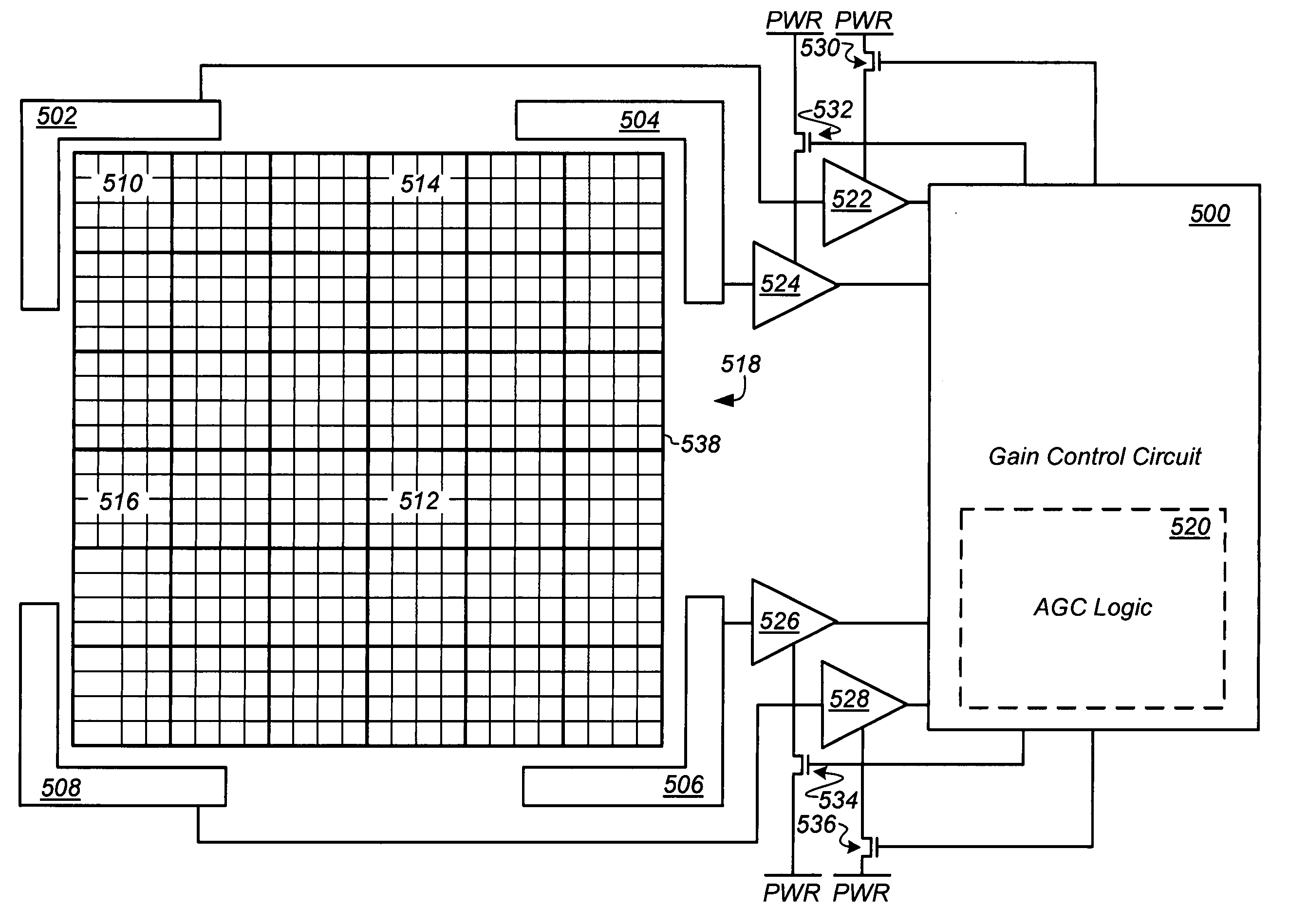
[0013]The present invention is directed generally to optical navigation systems and more particularly to a control circuit and method for use with an optical navigation system having redundant arrays to reduce power consumption therein.

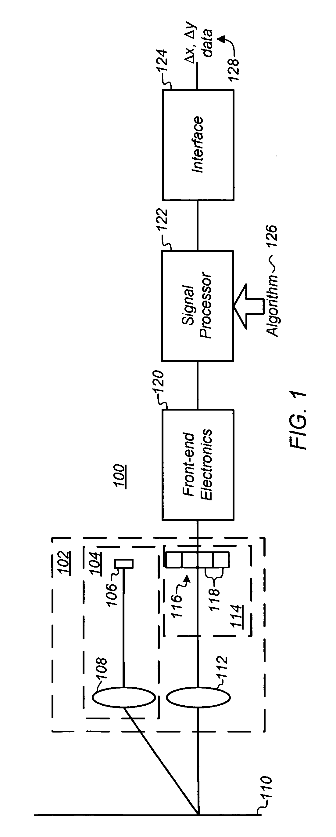
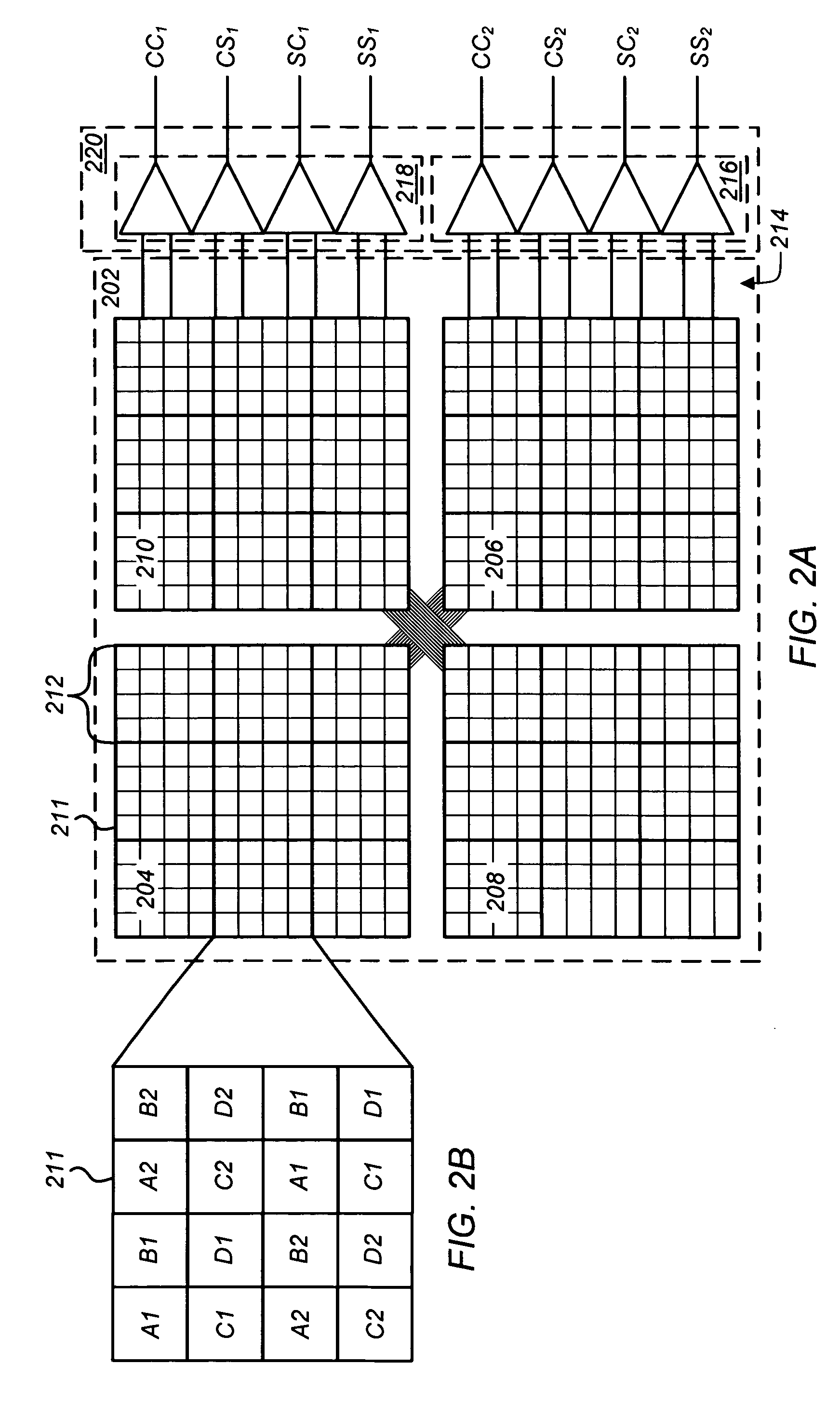
[0014]Optical navigation systems can include, for example, an optical computer mouse, trackballs and the like, and are well known for inputting data into and interfacing with personal computers and workstations. For purposes of clarity, many of the details of optical navigation systems in general and optical sensors for optical navigation systems in particular that are widely known and are not relevant to the present invention have been omitted from the following description. Optical navigation systems and optical sensors are described, for example, in co-pending, commonly assigned U.S. patent application Ser. No. 11 / 355,551, entitled, “Circuit and Method for Determining Motion with Redundant Comb-Array,” filed on Feb. 16, 2006 by Yansun Xu et al., an...


PUM


Abstract

A circuit and method are provided for reducing power consumption in an optical navigation system for use in an input device to sense displacement of the device relative to a surface. Generally, the system includes: (i) an optical sensor having at least first and second arrays of photosensitive elements; (ii) imaging optics to map an illuminated portion of the surface to the optical sensor; (iii) a signal processor including a first and second sensor circuits coupled to the respective first and second arrays to generate from each array a set of signals in response to motion of light received thereon; and (iv) a control circuit capable of independently switching power to the sensor circuits. In one embodiment, the control circuit powers down one sensor circuit when the strength of the set of signals from the other is greater than a predetermined minimum thereby maintaining device performance. Other embodiments are also disclosed.

Description

TECHNICAL FIELD[0001]The present invention relates generally to optical navigation systems, and more particularly to a circuit and method for use with an optical navigation system having redundant array to reduce power consumption therein.BACKGROUND OF THE INVENTION[0002]Optical navigation systems used in devices, such as an optical computer mouse, trackball or touch pad, are well known for inputting data into and interfacing with personal computers and workstations. Such devices allow rapid relocation of a cursor on a monitor, and are useful in many text, database and graphical programs. A user controls the cursor, for example, by moving the mouse over a surface to move the cursor in a direction and over distance proportional to the movement of the mouse. Alternatively, movement of the hand over a stationary device may be used for the same purpose.[0003]One technology used for optical mice today relies on a light source illuminating a surface, and a two-dimensional (2D) array of ph...

Claims


Application Information

Patent Timeline
Patent Type & Authority Patents(United States)
IPC IPC(8): G01J1/32
CPCG01J1/32
Inventor TODOROFF, BRIAN D.XU, YANSUN
Owner CYPRESS SEMICON CORP
Learn More