
Multi-domain clock skew scheduling

a multi-domain clock and scheduling technology, applied in the field of multi-domain clock skew scheduling, can solve the problems of significant limitation of the application of general clock skew scheduling is practically limited, etc., and achieve the effect of increasing the implementable optimization potential of the clock adjustment and limiting the optimization potential of the circuit design

Inactive Publication Date: 2007-11-13
CADENCE DESIGN SYST INC
View PDF2 Cites 32 Cited by
  • Summary
  • Abstract
  • Description
  • Claims
  • Application Information

AI Technical Summary

Benefits of technology

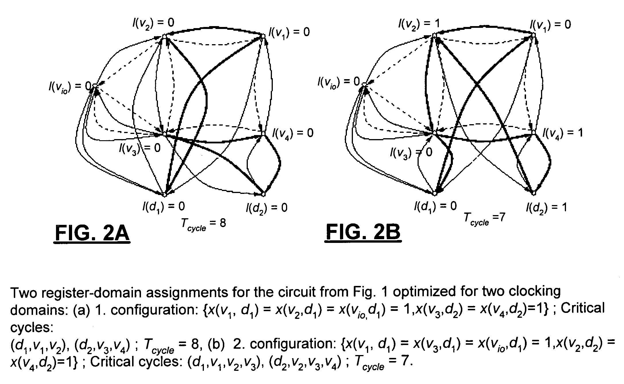
[0005]The present inventors have realized that application of general clock skew scheduling is practically limited due to the difficulties in implementing a wide spectrum of dedicated clock delays in a reliable manner, which results in a significant limitation of the optimization potential of a circuit design. In the present invention, the application of multiple clocking domains with dedicated phase shifts are implemented by reliable design structures that overcome these limitations and substantially increase the implementable optimization potential of clock adjustments.
[0009]The present invention is based on a branch-and-bound search for the assignment of registers to clocking domain[s]. In one embodiment, a satisfiability (SAT) solver based on a problem encoding in conjunctive normal form (CNF) is utilized to efficiently drive the search and compactly record parts of the solution space that are guaranteed to contain no solutions better than the current one. The combination of a modern SAT solver with an underlying orthogonal optimization problem provides a powerful mechanism for a hybrid search that also has significant potential for other applications in many domains.

Problems solved by technology

The present inventors have realized that application of general clock skew scheduling is practically limited due to the difficulties in implementing a wide spectrum of dedicated clock delays in a reliable manner, which results in a significant limitation of the optimization potential of a circuit design.

Method used


Image

  • Multi-domain clock skew scheduling
  • Multi-domain clock skew scheduling
  • Multi-domain clock skew scheduling

Examples


Embodiment Construction

[0018]The present invention is now described first by looking at unconstrained clock skew scheduling which is then extended to the constrained case.

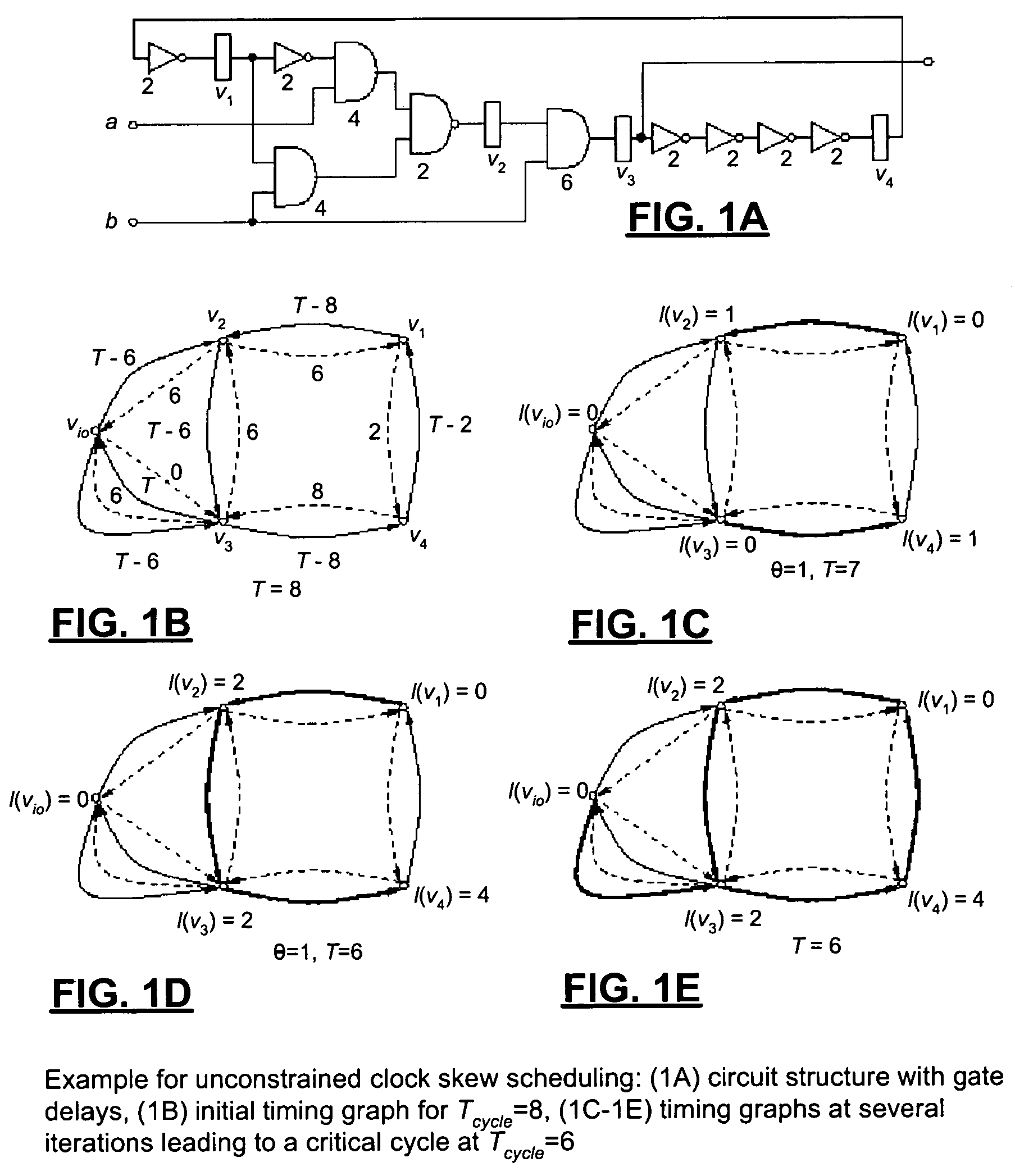
[0019]Given a sequential circuit, the objective of generic clock skew scheduling is to determine an assignment of latencies to registers in order to minimize the clock period, while avoiding clocking hazards. Let G=(V,Esetup,Ehold) denote the timing graph for a sequential circuit. The set of vertices V corresponds to the registers in the circuit and includes a single vertex for all circuit ports. The sets Esetup⊂V×V and Ehold⊂V×V denote the setup edges and hold edges, respectively. Esetup contains for each set of combinational circuit paths between registers (or a port) u and v a directed edge e=(u,v) with weight w(u,v)=Tcyle−dmax(u,v)−dsetup(v), where dmax(u,v) represents the longest combinational delay among all paths between u and v, dsetup(v) denotes the setup time at v, and Tcycle is the cycle period. Ehold consists of a set of reve...


PUM


Abstract

The present invention provides a process for constrained clock skew scheduling which computes for a given number of clocking domains the optimal phase shifts for the domains and the assignment of the individual registers to the domains. For the within domain latency values, the algorithm can assume a zero-skew clock delivery or apply a user-provided upper bound. Experiments have demonstrated that a constrained clock skew schedule using a few clocking domains combined with small within-domain latency can reliably implement the full sequential optimization potential to date only possible with an unconstrained clock schedule.

Description

COPYRIGHT NOTICE[0001]A portion of the disclosure of this patent document contains material which is subject to copyright protection. The copyright owner has no objection to the facsimile reproduction by anyone of the patent document or the patent disclosure, as it appears in the Patent and Trademark Office patent file or records, but otherwise reserves all copyright rights whatsoever.BACKGROUND OF THE INVENTIONField of Invention[0002]Discussion of Background[0003]Clock skew scheduling, often denoted as “cycle stealing”, computes a set of individual delays for the clock signals of the registers and latches of synchronous circuits to minimize the clock period. The schedule globally tunes the latching of the state holding elements such that the delays of their incoming and outgoing paths are maximally balanced. The computed intentional differences in the clock arrival times, also referred to as “useful skew”, are then implemented by designing dedicated delays into the clock distributi...

Claims


Application Information

Patent Timeline
IPC IPC(8): G06F17/50
CPCG06F17/5045G06F2217/62G06F30/396G06F30/30
Inventor KUEHLMANN, ANDREASRAVINDRAN, KAUSHIKSENTOVICH, ELLEN
Owner CADENCE DESIGN SYST INC
Learn More