
System and method of phase encoding for high fidelity vibratory seismic data

a vibratory seismic and phase encoding technology, applied in the field of seismic exploration for subsurface hydrocarbons, can solve the problem of limited processing of collected seismic data, and achieve the effect of superior properties and better quality

Active Publication Date: 2007-11-13
CONOCOPHILLIPS CO
View PDF8 Cites 50 Cited by
  • Summary
  • Abstract
  • Description
  • Claims
  • Application Information

AI Technical Summary

Benefits of technology

[0018]In accordance with a first embodiment of the present invention, a method of seismic processing, analysis and/or acquisition is disclosed herein that is designed to allow the best phase

Problems solved by technology

In some cases, limited processing of the collected seismic data might be done in the field.

Method used


Image

  • System and method of phase encoding for high fidelity vibratory seismic data
  • System and method of phase encoding for high fidelity vibratory seismic data
  • System and method of phase encoding for high fidelity vibratory seismic data

Examples


Embodiment Construction

[0031]While this invention is susceptible of embodiment in many different forms, there is shown in the drawings, and will be described hereinafter in detail, some specific embodiments of the instant invention. It should be understood, however, that the present disclosure is to be considered an exemplification of the principles of the invention and is not intended to limit the invention to the specific embodiments or algorithms so described.

ENVIRONMENT OF THE INVENTION

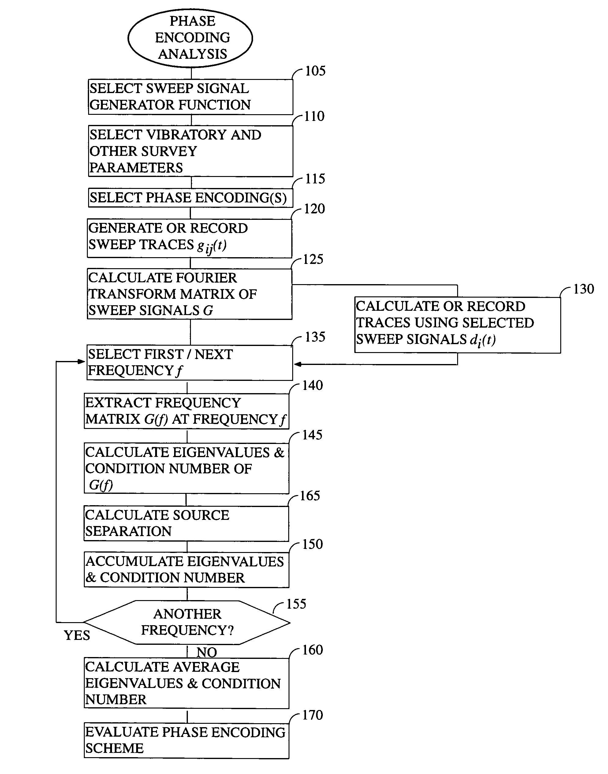
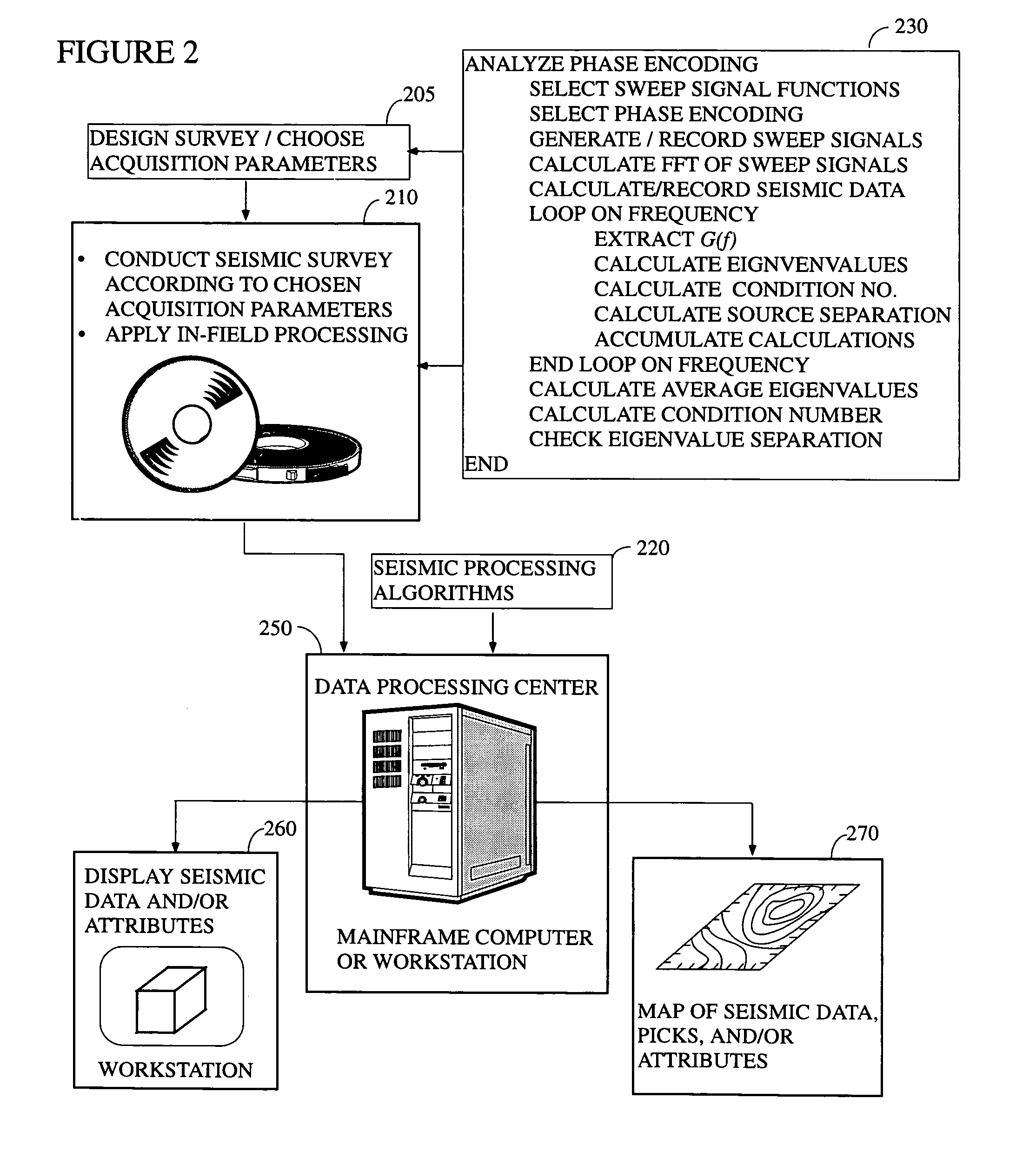
[0032]FIG. 2 illustrates the general environment in which the instant invention would typically be utilized. In the conventional arrangement, a seismic survey is planned according to methods well known to those of ordinary skill in the art (step 205). As part of the planning, the coverage area will be typically selected and various acquisition parameters will be specified. Among the acquisition parameters that might be specified at this stage include shot and receiver line and station spacing, number of recording channe...


PUM


Abstract

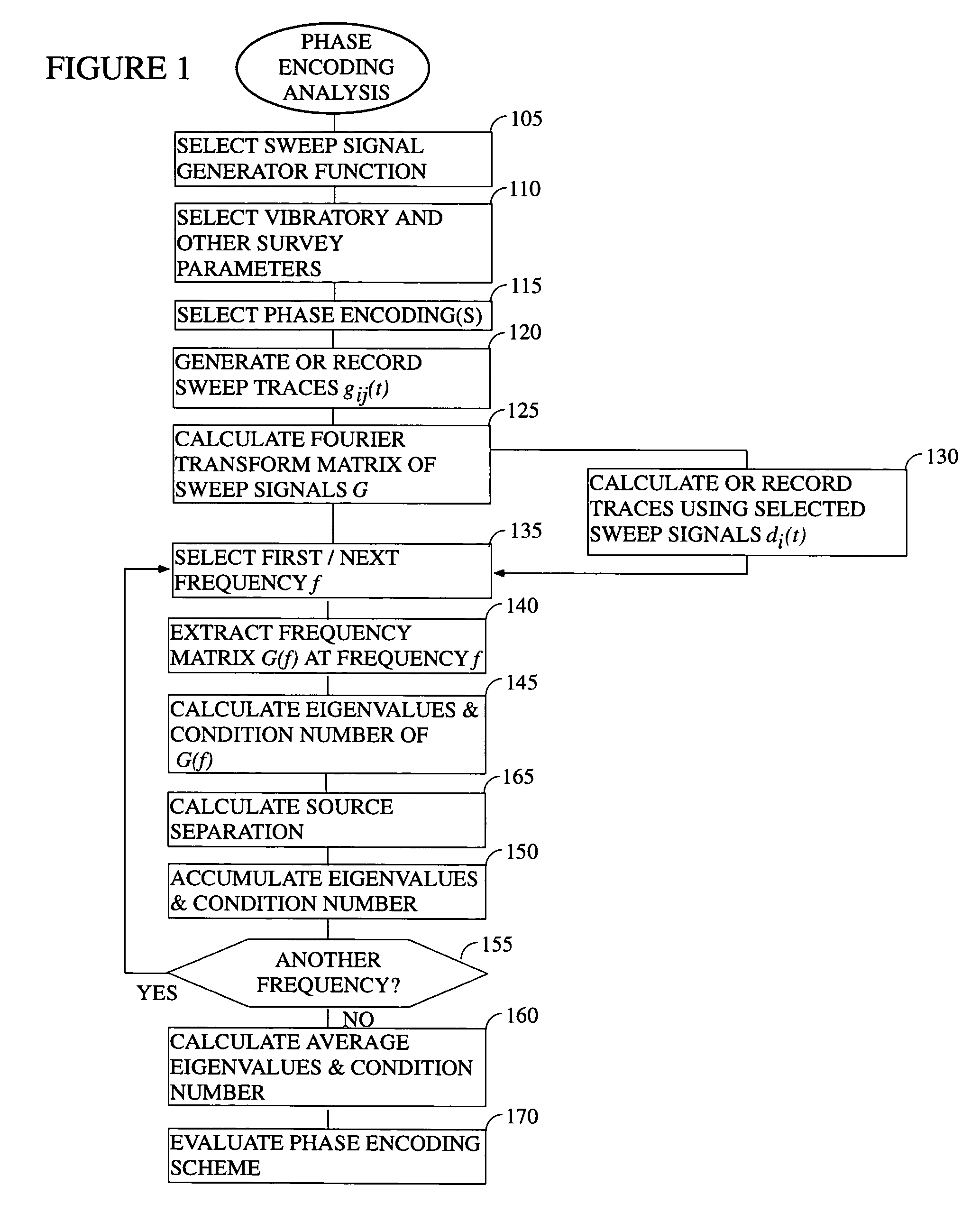
In accordance with the present invention, there is provided a method of determining whether a particular high fidelity vibratory seismic survey phase encoding is likely to be a good one based on an analysis of the eigenvalue structure (i.e., eigenvalues, eigenvalue separation, condition number, and model resolution matrix) of a matrix formed from the Fourier transforms of the sweep signals. Preferably, a singular value decomposition will be used to calculate the eigenvalues. Using this same approach, the condition number and eigenvalues of matrices that are associated with multiple proposed designs can be compared with each other to determine which is likely to be yield the best seismic data. This approach is preferably used either as a component of the advanced planning for a survey or in the field during pre-survey testing. The use of the instant approach to determine an optimal phase encoding scheme is also taught.

Description

TECHNICAL FIELD[0001]This invention relates to the general subject of seismic exploration for subsurface hydrocarbons and, in particular, to seismic acquisition and to methods for improving the quality of seismic data.BACKGROUND OF THE INVENTION[0002]The principal goal of a seismic survey is to image or map the subsurface of the earth by sending energy down into the ground and recording the reflected energy or “echoes” that return from the rock layers below. The source of the down-going sound energy might take many forms but is usually generated by an explosion or seismic vibrators on land, or air guns in marine environments.[0003]During a seismic survey, the energy source is systematically positioned at a variety of locations on or near the surface of the earth above a geological structure of interest. In a typical survey, each time the source is activated it generates a seismic signal that travels downward through the earth, is partially reflected, and, upon its return, is recorde...

Claims


Application Information

Patent Timeline
IPC IPC(8): G01V1/28
CPCG01V1/005
Inventor CHIU, STEPHEN K.EICK, PETER M.EMMONS, CHARLES W.
Owner CONOCOPHILLIPS CO
Learn More