
Flip-chip light-emitting device with micro-reflector

a micro-reflector and light-emitting device technology, applied in the direction of semiconductor devices, basic electric elements, electrical appliances, etc., can solve the problems of limited light-emitting angle, limited viewing angle, and easily identifiable source of inefficiency, and achieve the effect of improving light extraction

Active Publication Date: 2007-11-13
FORMOSA EPITAXY INCORPORATION
View PDF19 Cites 89 Cited by
  • Summary
  • Abstract
  • Description
  • Claims
  • Application Information

AI Technical Summary

Benefits of technology

[0006]It is therefore a primary objective of the claimed invention to provide a flip-chip light-emitting device with a micro-reflector. The micro-reflector includes a transparent patterned light-emitting stack layer. The transparent patterned light-emitting stack layer may be formed into a variety of shapes, including semicircular, pyramidical, conical, and so on, and can be continuous or discontinuous. The transparent patterned light-emitting stack layer is generated by means of etching on a light-emitting stack layer of the flip-chip light-emitting device, of evaporation deposition, or of a bonding method. Then, a reflective layer is formed over the transparent patterned light-emitting stack layer by means of evaporation deposition, so that the reflective layer includes the specific shapes to form a micro-reflector. The micro-reflector reflects vertical light with incoming light provided by a light-emitting area, so that the normal incidence light is un-affected by the critical angle for improving light extraction.

Problems solved by technology

Nevertheless, the prior art method, due to the reason that only light emitted at an angle within the critical angle θc would be completely emitted out, and other light would be reflected and absorbed, has a limited viewing angle and a readily identifiable source of inefficiency in the form of internal absorption of emitted light.
When light generated within the flip-chip light-emitting device travels from a material with a high refractive index to a material with a low refractive index, the angle of light emitted is limited due to the effect of said refractive indexes.
Therefore, an important issue is how to improve the efficiency of light emission, with respect to both viewing angle and intensity.

Method used


Image

  • Flip-chip light-emitting device with micro-reflector
  • Flip-chip light-emitting device with micro-reflector
  • Flip-chip light-emitting device with micro-reflector

Examples


Embodiment Construction

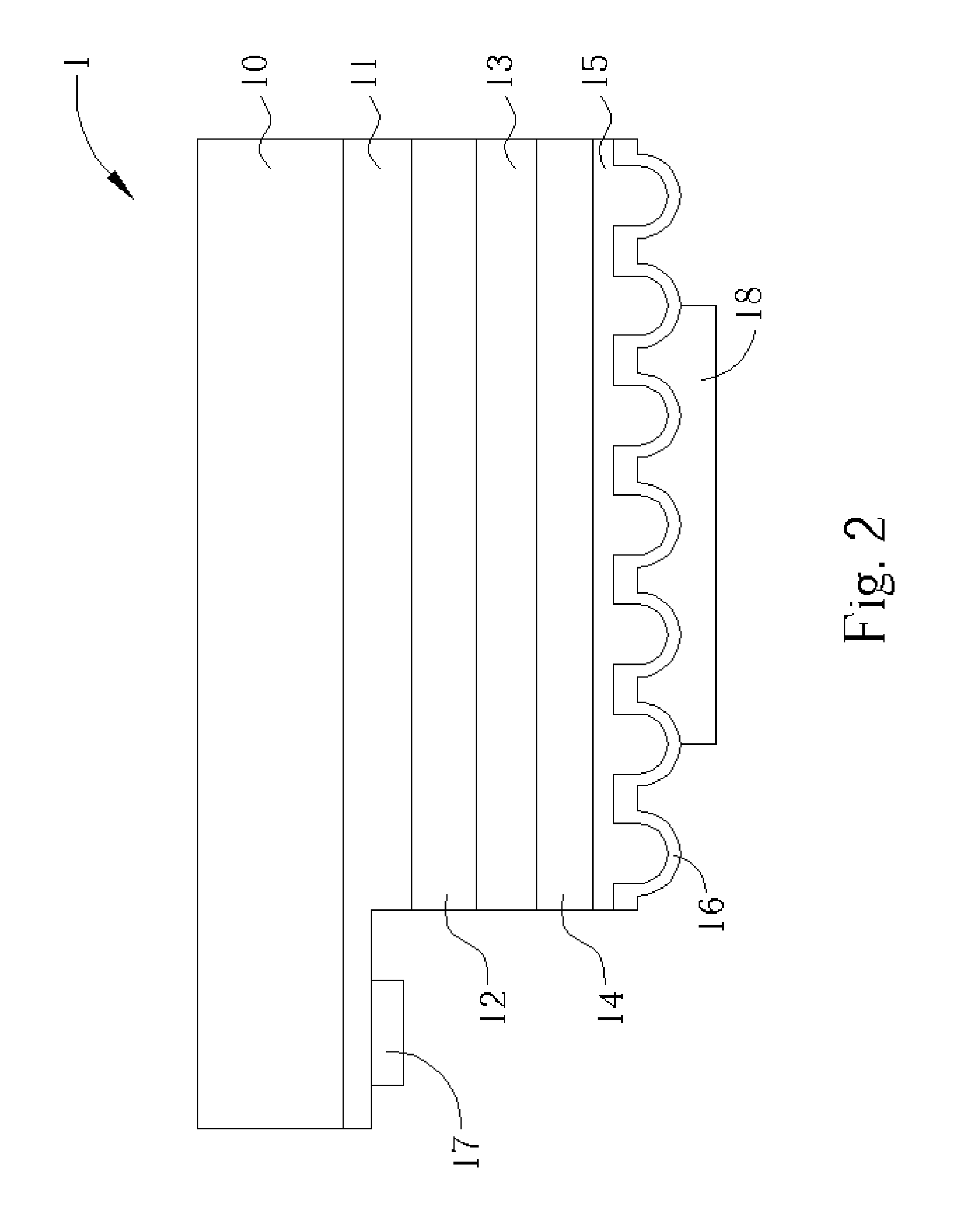
[0014]Please refer to FIG. 2, which illustrates a schematic diagram of a flip-chip light-emitting device 1 with a micro-reflector. The light-emitting device 1 includes a transparent substrate 10, a first contact layer 11 with a first surface and a second surface on an upper surface formed over the transparent substrate 10, a first cladding layer 12 formed over the first surface, a light-emitting layer 13 formed over the first cladding layer 12, a second cladding layer 14 formed over the light-emitting layer 13, a micro-reflector with a second contact layer 15 formed over the second cladding layer 14, a reflective layer 16 formed over the second contact layer 15, a first electrode 17 formed over the second surface, and a second electrode 18 formed over the reflective layer 16. The second contact layer 15 includes transparent patterned shapes, which can be continuous, or discontinuous.

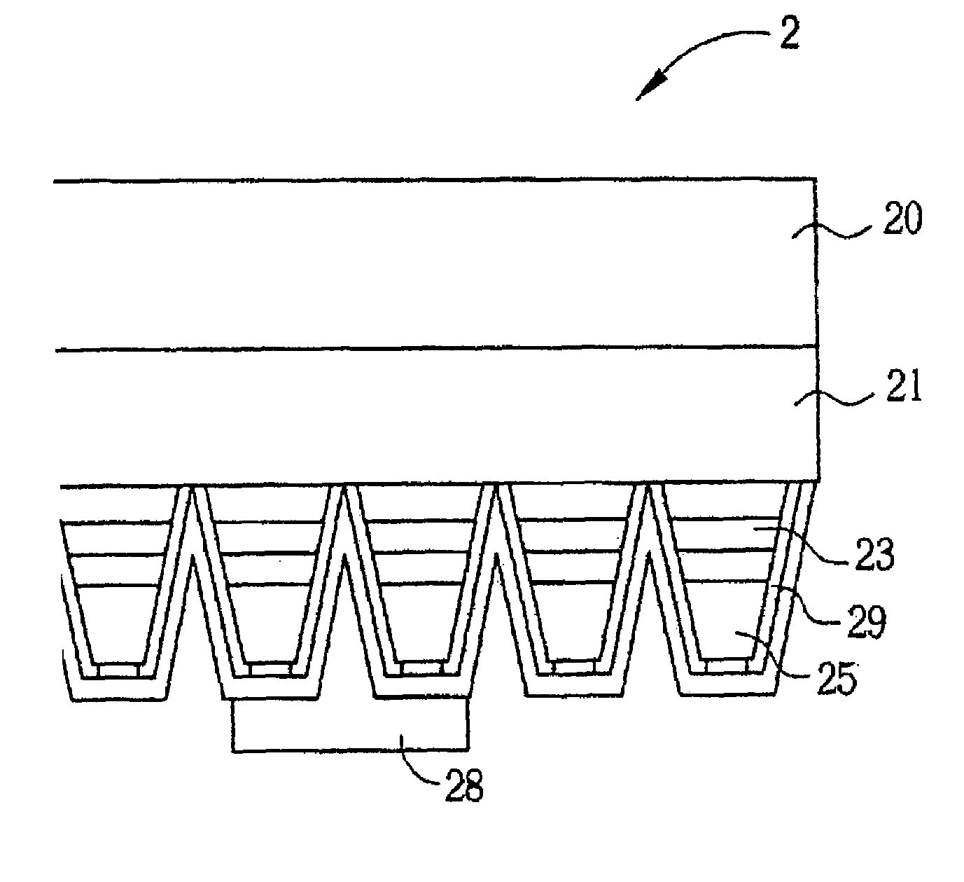
[0015]Please refer to FIG. 3, which illustrates a schematic diagram of a lightemitting device 2 with ...


PUM


Abstract

A Flip-chip light-emitting device with integral micro-reflector. The flip-chip light-emitting device emits reflected light provided by a light-emitting layer. The micro-reflector reflects light that might otherwise be lost to internal refraction and absorption, so as to increase light-emitting efficiency.

Description

BACKGROUND OF INVENTION[0001]1. Field of the Invention[0002]The present invention provides a light-emitting device, and more particularly, a flip-chip light-emitting device with a micro-reflector.[0003]2. Description of the Prior Art[0004]The applications of light-emitting diodes are extensive and include optical display devices, traffic signals, data storing devices, communication devices, illumination devices, and medical apparatuses. As such, it is important to increase the brightness of light-emitting diodes, and to simplify manufacturing processes in order to decrease the cost of the light-emitting diode.[0005]Please refer to FIG. 1, which illustrates a schematic diagram of a flip-chip light-emitting device and its related method of manufacture disclosed in TW patent 441 859, in which a first electrode and a second electrode of the flip-chip light-emitting device bring reflected light out from a light-emitting layer. Nevertheless, the prior art method, due to the reason that on...

Claims


Application Information

Patent Timeline
Patent Type & Authority Patents(United States)
IPC IPC(8): H01L27/15H01L29/24H01L29/22H01L33/02H01L33/42H01L33/62
CPCH01L33/08H01L33/20H01L33/405
Inventor LIU, WEN-HUANG
Owner FORMOSA EPITAXY INCORPORATION
Learn More