
Grinding plate for an electric hand grinder, and method of producing the same

a technology of electric hand grinder and grinding plate, which is applied in the direction of auxillary shaping apparatus, edge grinding machine, manufacturing tools, etc., can solve the problems of difficult removal of abrasion traces and relatively expensive foam process, and achieve the effect of separating cuts

Inactive Publication Date: 2007-11-13
ROBERT BOSCH GMBH
View PDF6 Cites 0 Cited by
  • Summary
  • Abstract
  • Description
  • Claims
  • Application Information

AI Technical Summary

Benefits of technology

The present invention provides a grinding plate for an electric hand grinder that avoids the disadvantages of prior art. The grinding plate has a side surface with a pagoda-shaped contour that allows for a grinding edge lip with great yielding ability. This results in finer grinding operations and allows for transitions and damages to the workpiece to be avoided. The grinding plate is simple and cost-favorable to manufacture and can be produced from existing materials. The method of producing the grinding plate involves punching out a plate body with an upper plate surface, a lower plate surface, and a side surface, and separating the squeezed out material along an outer edge of the round bar with a separating cut. The grinding plate can be made from cellular rubber and has a circular ring-shaped grinding edge. The invention provides a solution for improving the grinding performance of electric hand grinders.

Problems solved by technology

Such abrasion traces are difficult to remove, in particular on bright surfaces.
These foam processes are however relatively expensive.

Method used


Image

  • Grinding plate for an electric hand grinder, and method of producing the same
  • Grinding plate for an electric hand grinder, and method of producing the same
  • Grinding plate for an electric hand grinder, and method of producing the same

Examples


Embodiment Construction

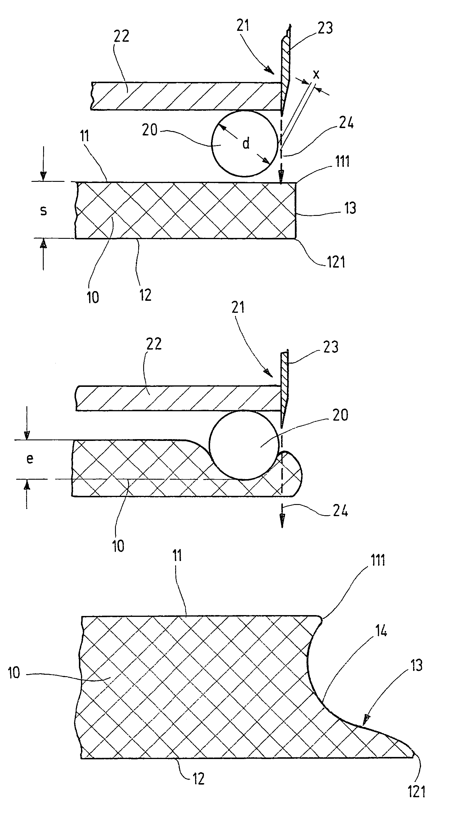
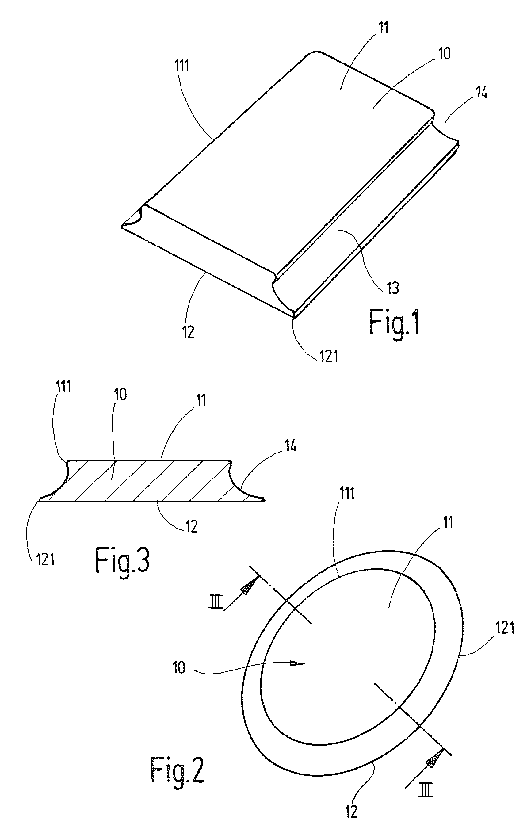
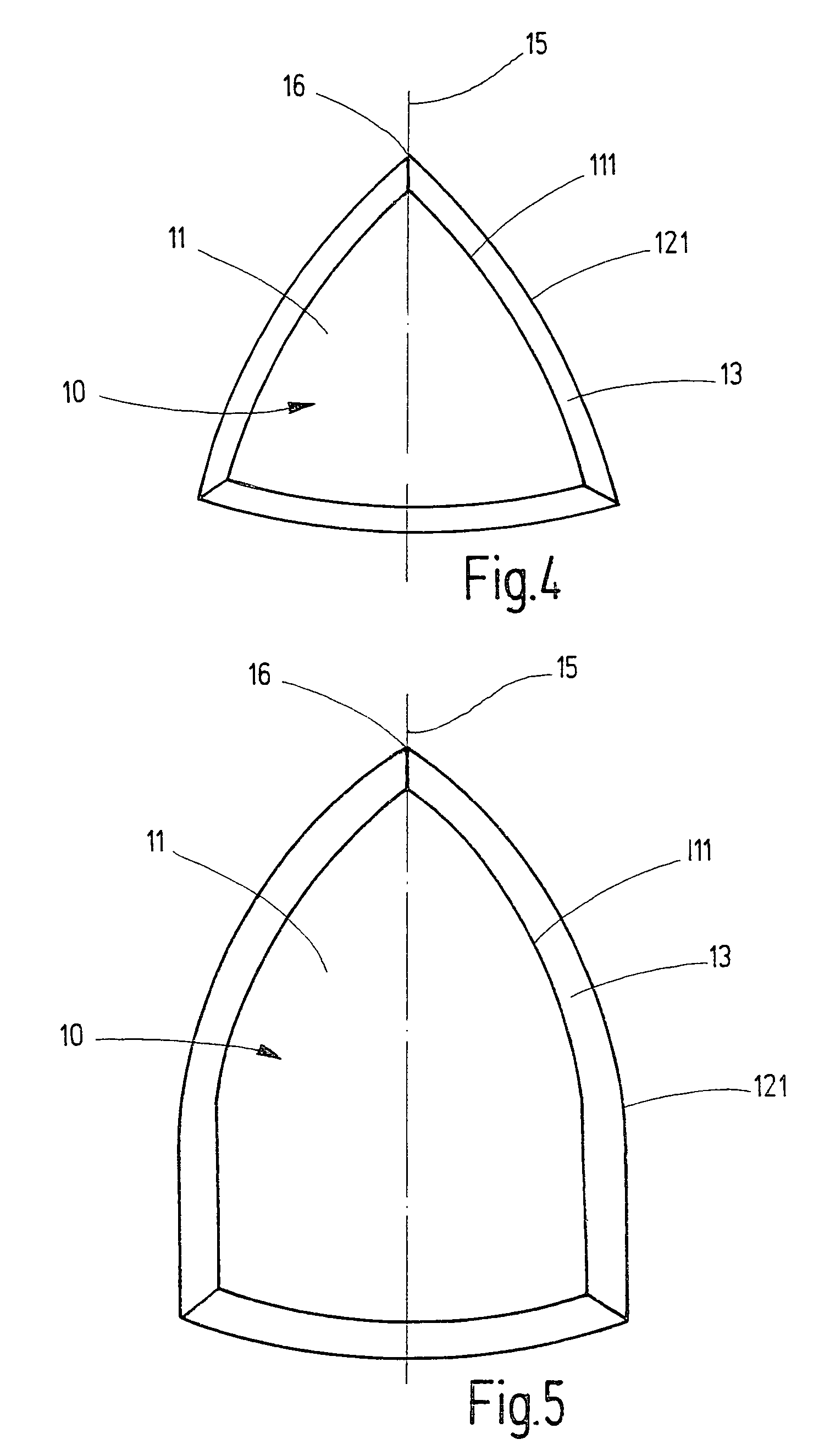
[0027]A grinding plate for a vibration grinder is shown in perspective in FIG. 1 as an example for a general electric hand grinder. It has a rectangular plate body 10 composed of an elastic material and having an upper plane surface 11 placeable on a support of the vibration grinder, a lower plate surface 12 covered with a grinding means, for example a grinding plate or a grinding disc and side surfaces 13 extending from the upper plate edge 111 to the lower plate edge 121.

[0028]The lower plate surface 12 projects substantially far beyond the both longitudinal edges of the upper plate edge 11. The both side surfaces 13 which extend from the both longitudinal edges of the upper plate edge 111 correspondingly to the both longitudinal edges of the lower plate edge 121 each have a pagoda-shaped contour 14. Thereby in the region of the longitudinal edges on the lower plate edge 121, an elastic grinding edge lip is produced, which is displaced forwardly relative to the plate body 10 at a ...


PUM

PropertyMeasurementUnit
diameteraaaaaaaaaa
diameteraaaaaaaaaa
thicknessaaaaaaaaaa

Abstract

A grinding plate for an electric hand grinder has a plate member having an upper plate surface with an upper plate edge, a lower plate surface with a lower plate edge for placement of a grinding means and extending at least partially beyond the upper plate edge, and a side surface extending from the upper plate edge to the lower plate edge, and having a pagoda-shaped contour in a projecting region of the lower plate edge and the grinding plate is produced by a method including punching out the plate body with the upper surface, the lower surface and the side surface from an elastic material in a desired shape; placing a round bar on the upper plate surface along the upper plate edge of the plate body with a parallel distance from it; pressing the round bar into the plate body so that an elastic material of the plate body is squeezed outwardly under the round bar; separating the squeezed out material along an outer edge of the round bar with a separating cut extending perpendicular to the plate surfaces; and removing the round bar from the upper plate surface.

Description

BACKGROUND OF THE INVENTION[0001]This application is a division of U.S. application Ser. No. 10 / 684,551, filed Oct. 14, 2003 now abondoned, the disclosure of which is incorporated herein by reference.[0002]The present invention relates to a grinding plate composed of an elastic material for an electric hand grinder, and also to a method for producing the same.[0003]A known electric hand grinder formed for example as a vibration grinder or an eccentric grinder (DE 35 10 333 A1) has a grinding medium support composed of a driven, rigid support part and an elastic grinding plate which is fixed with an upper plate surface on the support part. Its lower plate surface is provided with a receptacle of a grinding means, for example a grinding plate or a grinding disc. For obtaining a high grinding yield, the grinding plate has a predetermined Shore hardness. Such a grinding plate is produced in a cost-favorable manner by punching out of a large-surface sheet and glueing to the support part....

Claims


Application Information

Patent Timeline
Patent Type & Authority Patents(United States)
IPC IPC(8): B24B9/20B24B23/02B24B23/04B24D9/08
CPCB24B23/02B24D9/08B24B23/04
Inventor WUENSCH, STEFFEN
Owner ROBERT BOSCH GMBH
Learn More