
Multiplexing control system and multiplexing method therefor

a control system and multiplexing technology, applied in the field of multiplexing control system and multiplexing method therefor, can solve the problems of increasing the number of parts, affecting the quality of the product, so as to reduce the amount of hardware, size and cost, cost reduction

Inactive Publication Date: 2007-11-06
HITACHI LTD
View PDF21 Cites 5 Cited by
  • Summary
  • Abstract
  • Description
  • Claims
  • Application Information

AI Technical Summary

Benefits of technology

[0010]The present invention is carried out for countermeasuring the above problems and a first object of the present invention is to provide a multiplexing control system which shows fast response characteristic and high reliability.
[0011]Further, a second object of the present invention is to provide a low cost, high reliability and small sized multiplexing control system and a multiplexing method therefor.
[0013]More specifically, regardless to the number of microcomputers through the use of comparable number of interface broads as the number of microcomputers in a single input / output hard interface unit, the input / output hard interface unit can be used in common, thereby, inputting / outputting can be performed in parallel without using the transmission which drastically shortens the control time.
[0014]Through thus constituting, no process signal transmission time is required, thereby, a multiplexing control having a fast response characteristic and a high reliability can be achieved.
[0018]Still further, the object of the present invention can be achieved in such a manner that one process input / output unit which inputs and outputs the process signals with a plant is provided for every process signal and the redundancy structure of the input / output units for inputting and outputting process signals are either triplexed, diplexed or monoplexed depending on importance of the process signals. Namely, not triplexing all of the units constituting the plant control device only the units for the process signals having high importance are triplexed and other units are either diplexed or monoplexed, thereby, the amount of hardware can be reduced and the size and cost reduction of the device can be realized without damaging reliability.
[0019]Further, since the system is constituted so that the process controller having the master right supports all of the units, a further cost reduction thereof can be realized.

Problems solved by technology

With one of the above conventional art in which the system is constituted by connecting each process input / output unit independently to each of the three processor units in a redundant structure, even if a single input sensor is sufficient for an input signal, such as an amplifier is required for inputting the signal into the three process input units, and further the output signals outputted from the three process output units require at the outside thereof a circuit which selects one of the output signals for the plant which arises problems with regard to cost and size thereof.
Further, when all of the signals inputted / outputted to and from the-process control unit are connected to the process input / output unit in this scheme, these circuits become huge, thereby, the failure rate rises as well as number of parts increases which is undesirable from a view point of maintenance.
Still further, with the above conventional art in which inputting / outputting of process-variables and monitoring thereof in a multiplexed control system are performed through a separate provision of a microcomputer exclusive for the monitoring and an input / output hard interface unit, it requires a transmission time which increases a response time and arises a problem of necessitating a long control time.
Still further, with the conventional art disclosed in JP-A-08-106301 since the processor units and the process input / output unit are connected via triplexed lines as well as a circuit for connection change-over is provided for each of the process input / output units, the circuit thereof complexes in comparison with a usual process input / output unit and a problem arises that a significant cost increase can not be avoided in order to keep reliability when using the hard wire circuits.

Method used


Image

  • Multiplexing control system and multiplexing method therefor
  • Multiplexing control system and multiplexing method therefor
  • Multiplexing control system and multiplexing method therefor

Examples


Embodiment Construction

[0039]Hereinbelow, an embodiment according to the first invention will be explained.

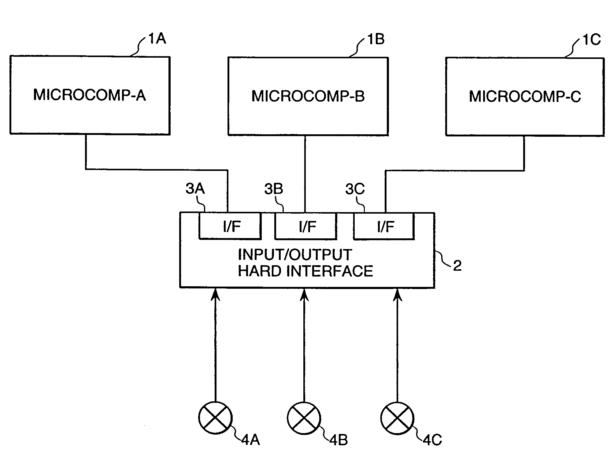
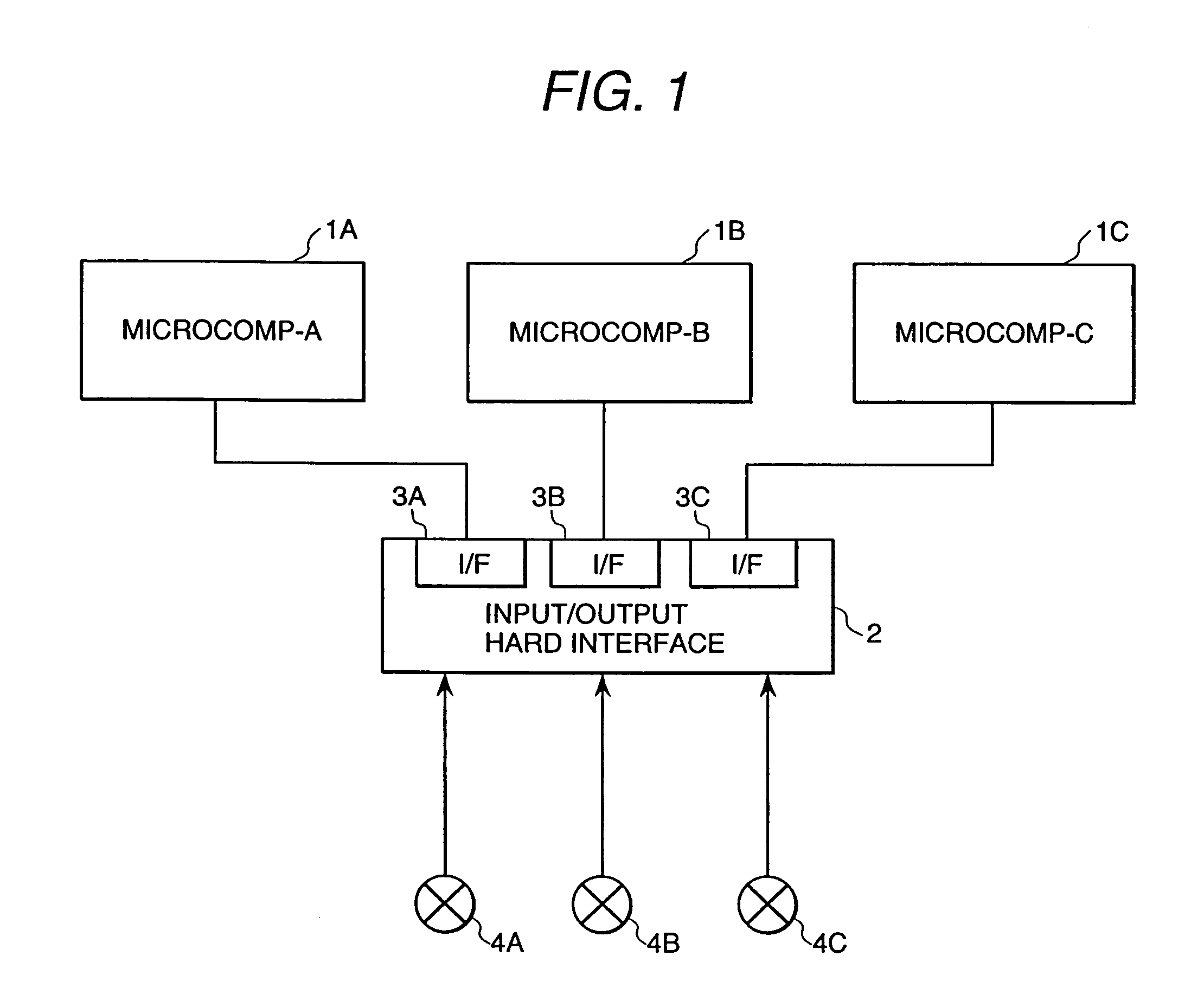
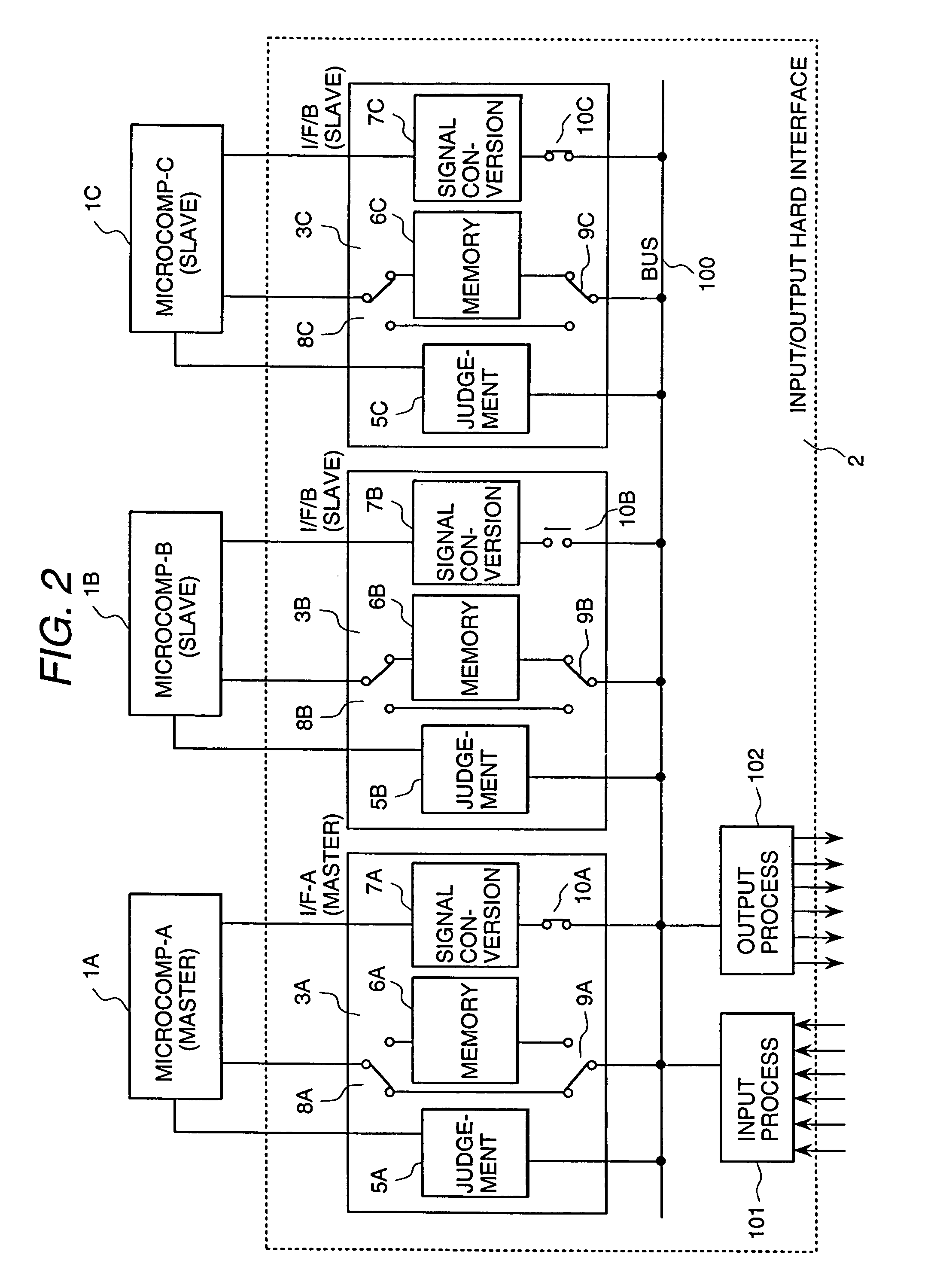
[0040]FIGS. 1 and 2 show a structure of a multiplexed control system (through triplexing microcomputers) representing an embodiment according to the present invention.

[0041]The multiplexed control system as shown in FIG. 1 is constituted by three microcomputers (1A-1C) and an input / output hard interface 2 provided in common for the three microcomputers, and the input / output hard interface 2 is inputted of process signals from three sensors (4A-4C) and distributes the process signals to the microcomputers (1A-1C) via interface boards (3A-3C).

[0042]FIG. 2 shows the detailed structure of the multiplexed control system as shown in FIGS. 1, 1A, 1B and 1C are microcomputers, 5A, 5B and 5C are judgement units, 6A, 6B and 6C are memories, 7A, 7B and 7C are signal conversion units, 101 is an input / output processing unit and 102 is an output processing unit, and the system performs the following operations.

[00...


PUM


Abstract

A multiplexing control system has a common process input / output unit for distributing process signals from sensors for measuring the same state variable of a process to digital controllers. One process input / output unit for inputting / outputting a process signal between the multiplexing control system and plant is provided for each process signal. The process input / output unit for the process signal of high importance is triplexed. A process controller having an operating function is provided to each of the triplexed process input / output units. A process input / output unit for the process signal of intermediate importance is diplexed. A process input / output unit for the process signal of low importance is monoplexed. The process signals of the diplexed process input / output units and the monoplexed process input / output unit are controlled by a controller having a master right among the process controllers.

Description

CROSS-REFERENCE TO RELATED APPLICATION[0001]The present application is a continuation application of U.S. patent application Ser. No. 10 / 220,468, filed on Nov. 12, 2002, the disclosure of which is incorporated by reference herein.FIELD OF THE INVENTION[0002]The present invention relates to a multiplexing control system and a multiplexing method therefor in which processes in a variety of plants such as an electric power generation plant and a chemical plant are controlled by a digital controller of such as a plurality of microcomputers via a process input / output unit.BACKGROUND OF THE INVENTION[0003]With regard to such as recirculation pump control in nuclear power generation plants, gas turbine control and steam turbine control in thermal power generation plants and controls in variety of plants such as chemical plants, a stable operation thereof is demanded in the world, therefore, protective functions of particularly high importance for enhancing reliability and safety of the pla...

Claims


Application Information

Patent Timeline
Patent Type & Authority Patents(United States)
IPC IPC(8): G05B19/18G05B19/04G05B9/03G05B19/418
CPCG05B9/03G05B19/4184G05B2219/31229G05B2219/24189G05B2219/25432G05B2219/2231Y02P90/02
Inventor MIURA, KAZUHIKOTAKAHASHI, SHOEIASAKURA, KAZUYASUMARUYAMA, YOSHIOSHIMIZU, KATSUHITOMORI, YUKIKOAKATSU, TOHRU
Owner HITACHI LTD
Learn More