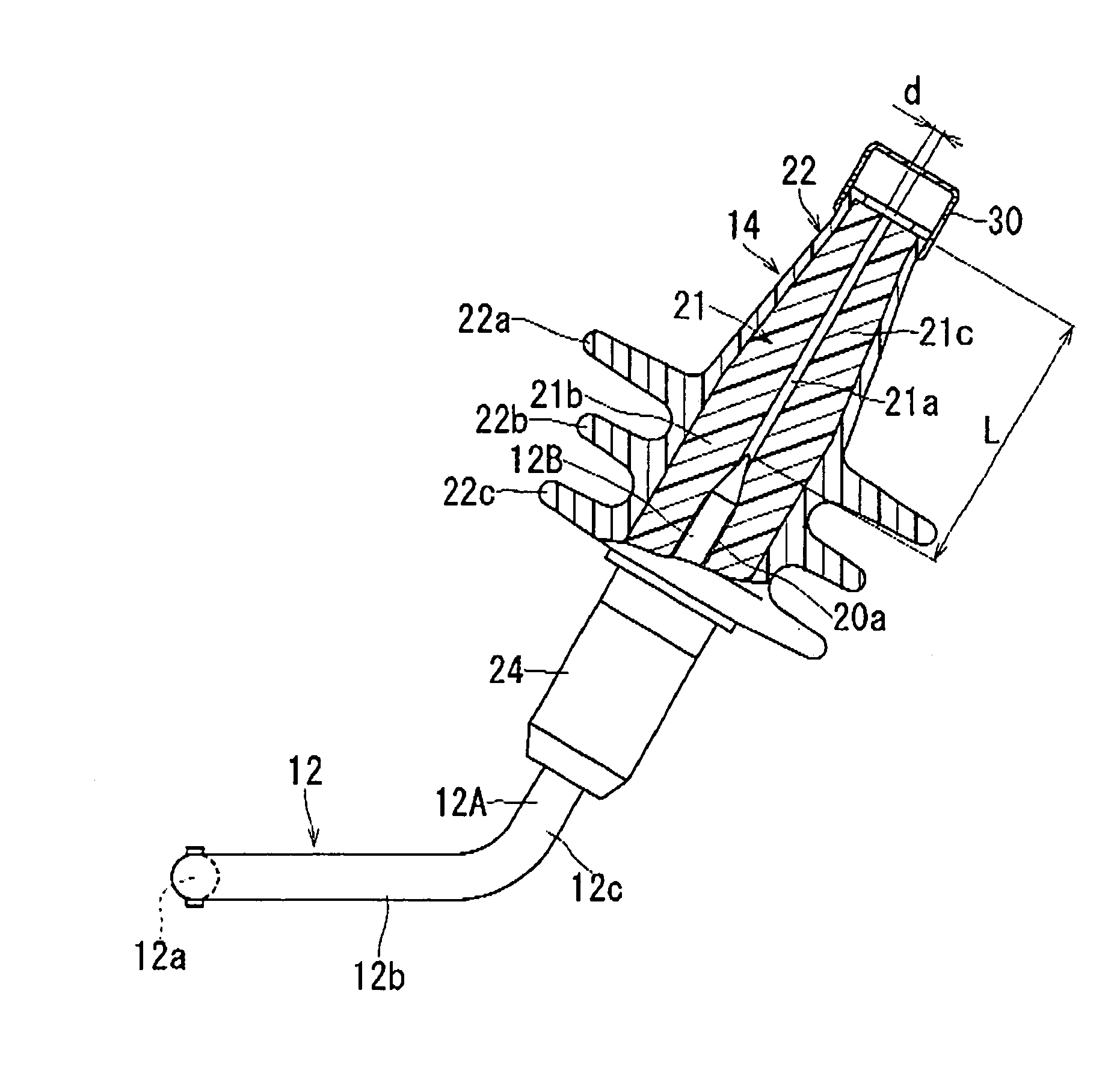
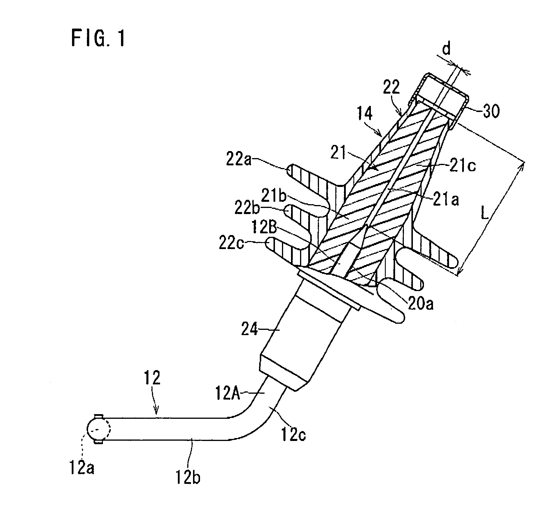
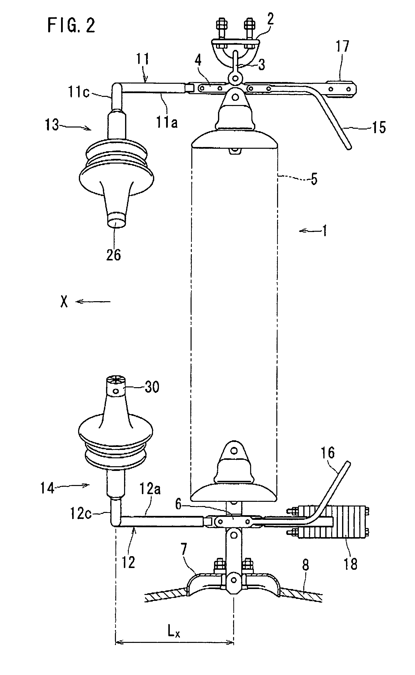
Arcing horn device
a horn and horn technology, applied in emergency protective circuit arrangements, emergency protective arrangements for limiting excess voltage/current, air-break switches, etc., can solve the problems of difficult to obtain sufficient difficult to generate arcs, and extremely reduced flashover properties, etc., to achieve good improve dynamic current shutoff capability
- Summary
- Abstract
- Description
- Claims
- Application Information
AI Technical Summary
Benefits of technology
Problems solved by technology
Method used
Image

Examples
first modified embodiment
[0151]In the next place, a modified embodiment of the cap 30 will be described below. At first, as same as the above cases in the cap 30 shown in FIG. 12 illustrating a first modified embodiment, the sectioned pieces 32a that are capable of being elastically transformed individually are formed by providing the slits 35 to the wall portion 32. However, a hole equivalent to the above mentioned penetration hole 34 is not particularly provided on its center but a gap like a needle hole is defined in the center.
[0152]Accordingly, it is possible to prevent the rain water from intruding into the lower part through the penetration hole 34 in the above case, so that, in the embodiment shown in the drawing, without providing the above mentioned space 33 between the wall portion 32 and the front end surface of the insulative member 14 and the above mentioned water drain opening 37 in the circular cylinder portion 31, this cap 30 is attached to the insulative member 14 as the front end surface ...
second modified embodiment
[0154]In FIGS. 13A and 13B showing a second modified embodiment, on the front end surface of the insulative member 14, the cap 30 only consisted of the movable body 36 that is substantially rectangular flat plate from the plane view is attached. This movable body 36 is manufactured by a soft vinyl chloride as same as the above and the thickness thereof is set in the thickness having a sufficient elastic transformation capability and then, at the end portion upper side (a left end side in the drawing), this movable body 36 is fixed on the circle coated portion 22d of the coating layer 22 in the insulative member 14 by a insulating screw bolt 39.
[0155]Upon the operation such that the arc jet is blown off, as shown in FIG. 13C, the above mentioned movable body 36 is depressed by the blowoff power of the arc jet GJ to be inflected and transformed, so that the movable body 36 is evacuated through a blowoff path of the arc jet GJ. Upon the nonaction, the movable body 36 returns to the pos...
third modified embodiment
[0156]The cap 30 shown in FIGS. 14A and 14B illustrating a third modified embodiment is provided with a frame 42 that is secured so as to surround the outer periphery of the front end side of the insulative member 14 and on the upper surface of this frame 42, the movable body 36 that is substantially rectangular flat plate from the plane view is attached. At the center of the frame 42, a penetration path 42a, of which diameter is rather smaller than that of the above mentioned circle coated portion 22d in the insulative member 14, is formed.
[0157]The movable body 36 is rotatably attached on the upper surface of the frame 42 at the upper end portion side (a left end side in the drawing) by an axis portion 42b around this axis portion 42b and the movable body 36 is retained on the upper end surface of a surrounding wall 42c to surround the above described penetration path 42a as abutting against this upper end surface of a surrounding wall 42c with a lid on this upper end surface. Alt...
PUM
| Property | Measurement | Unit |
|---|---|---|
| opening angle | aaaaa | aaaaa |
| opening angle | aaaaa | aaaaa |
| distance | aaaaa | aaaaa |
Abstract
Description
Claims
Application Information
 - R&D
- Intellectual Property
- Life Sciences
- Materials
- Tech Scout
- Unparalleled Data Quality
- Higher Quality Content
- 60% Fewer Hallucinations
Browse by: Latest US Patents, China's latest patents, Technical Efficacy Thesaurus, Application Domain, Technology Topic, Popular Technical Reports.
© 2025 PatSnap. All rights reserved.Legal|Privacy policy|Modern Slavery Act Transparency Statement|Sitemap|About US| Contact US: help@patsnap.com