Rotating back iron for synchronous motors/generators

Inactive Publication Date: 2007-11-06
RELIANCE ELECTRIC TECH
View PDF12 Cites 10 Cited by
  • Summary
  • Abstract
  • Description
  • Claims
  • Application Information

AI Technical Summary

Benefits of technology

[0007]The present invention provides a system to mitigate losses and improve efficiency in rotating synchronous machines. Eddy current losses are commonly found in synchronous motors having an air-core geometry. In conventional air-core motors, magnetic flux, which generates eddy current losses, passes across an air gap that separates stationary and moving components of the motors. To mitigate such losses, a motor / generator is provided that includes at least one rotating back iron. The back iron(s) is coupled to a drive shaft of the motor / generator and thus, is operable to rotate with rotor. Because the back iron(s) is not stationary, DC fields, rather than AC fields, are produced by rotating windings in the rotor. Accordingly, AC losses in the motor / generator will be mitigated and hence axial gap and radial gap topologies described herein facilitate improved flux containment over conventional topologies.
[0008]The motor / generator of the present invention can also include at least one permanent magnet located in the rotor. The permanent magnet(s) cooperates with rotor windings to generate a DC magnetic field for the rotor. The permanent magnet(s) also facilitates reduction of flux density perpendicular to the rotor windings. Operation of the motor / generator is also facilitated by the permanent magnet(s) when the rotor windings are not operational. A further benefit of the permanent magnet(s) is that the rotor can be configured with the permanent magnet(s) in a non-magnetized state. The rotor windings can then be used to magnetize the permanent magnet(s).

Problems solved by technology

The superconducting synchronous motors generally have an air-core geometry, which possess problems with end-winding and core end region eddy current losses due to a higher than normal leakage fields.
The circumferential / radial eddy currents generate high losses in the motors.

Method used


Image

  • Rotating back iron for synchronous motors/generators
  • Rotating back iron for synchronous motors/generators
  • Rotating back iron for synchronous motors/generators

Examples


Embodiment Construction

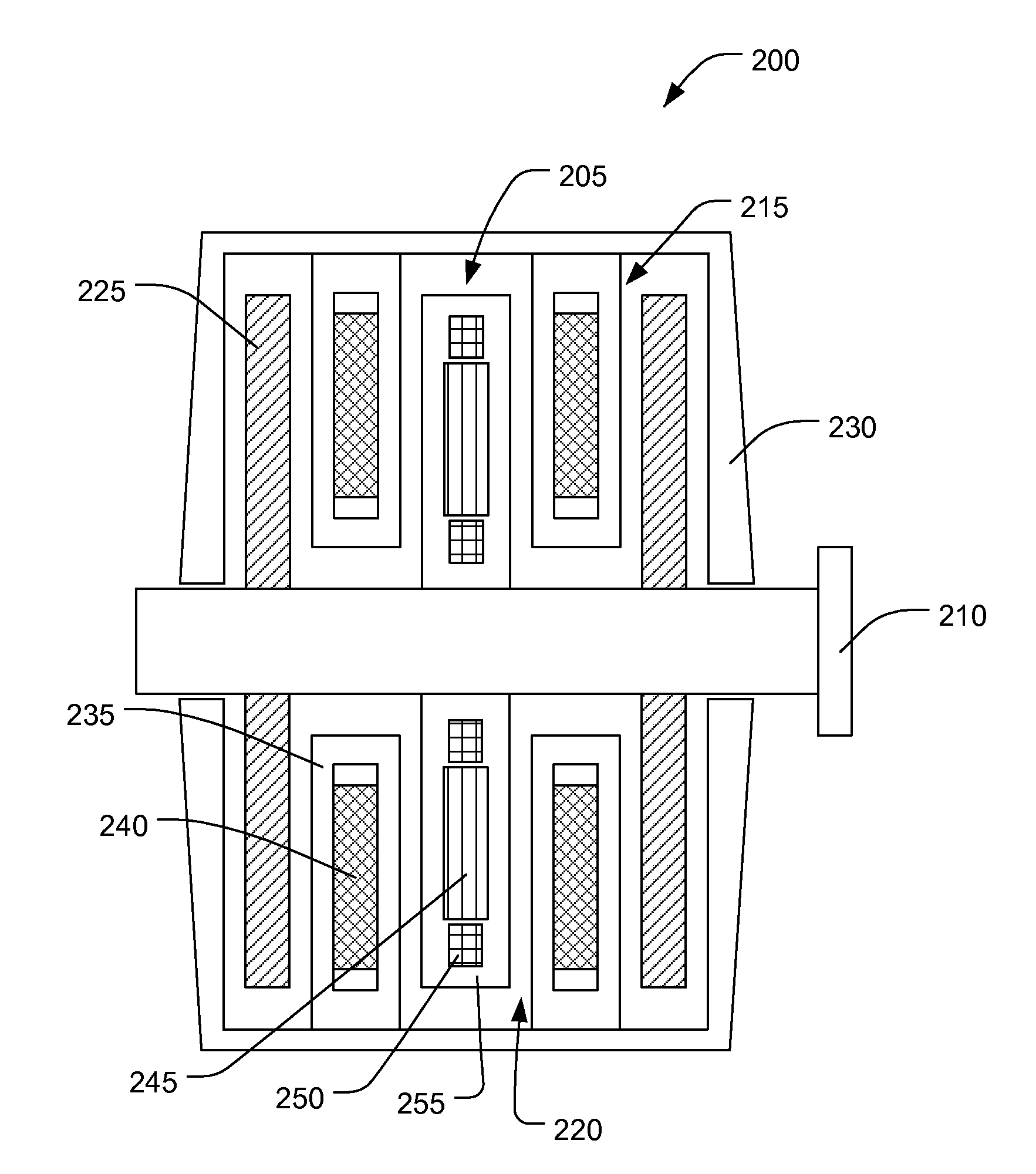
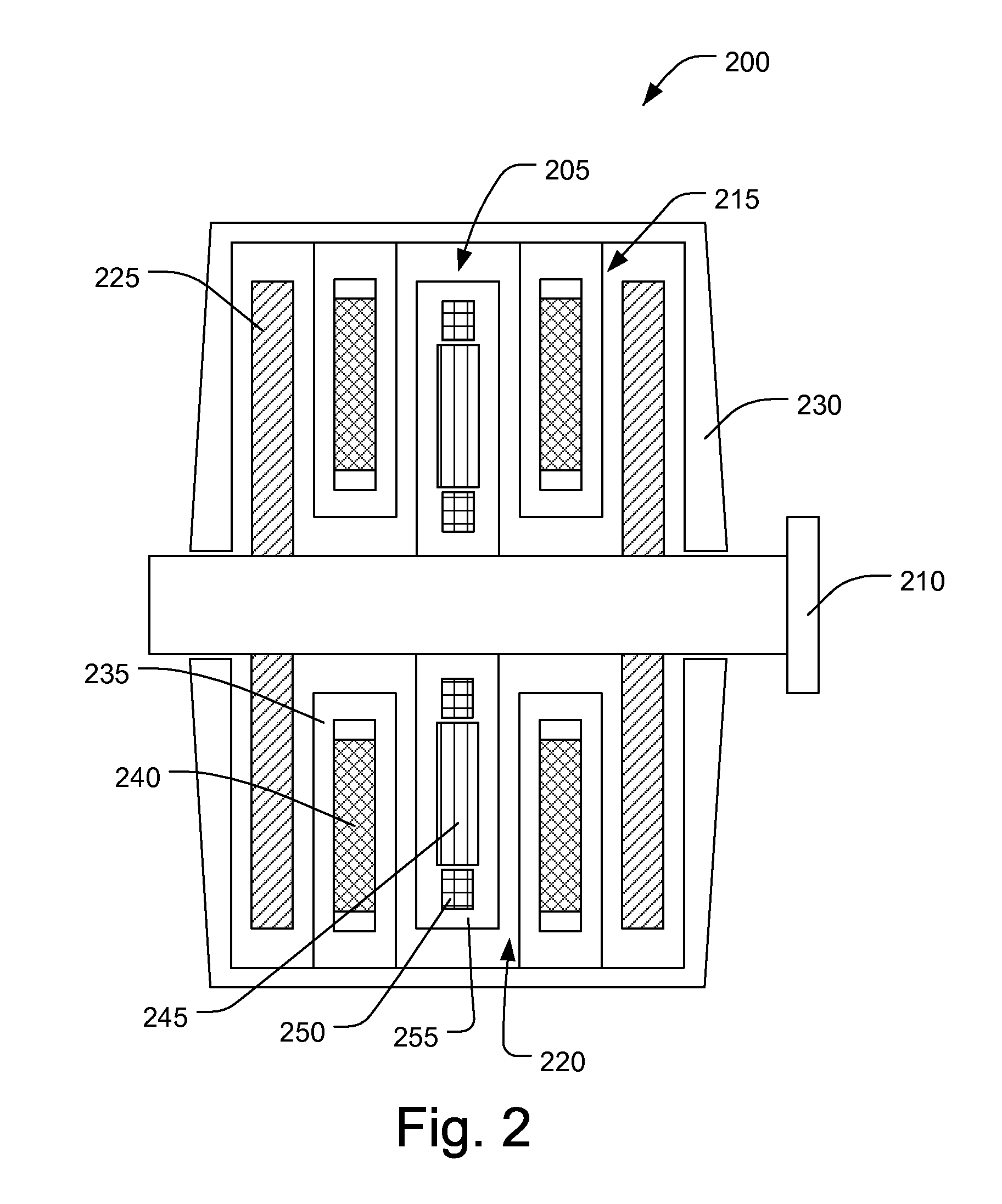
[0019]The present invention relates to systems and methods for a synchronous motor / generator including a stator winding supported in a non-conductive structure attached to the machine frame and a back iron element, which is rotated along with a rotor. The present invention is now described with reference to the drawings, wherein like reference numerals are used to refer to like elements throughout. In the following description, for purposes of explanation, numerous specific details are set forth in order to provide a thorough understanding of the present invention. It may be evident, however, that the present invention may be practiced without these specific details. In other instances, well-known structures and devices are shown in block diagram form in order to facilitate describing the present invention.

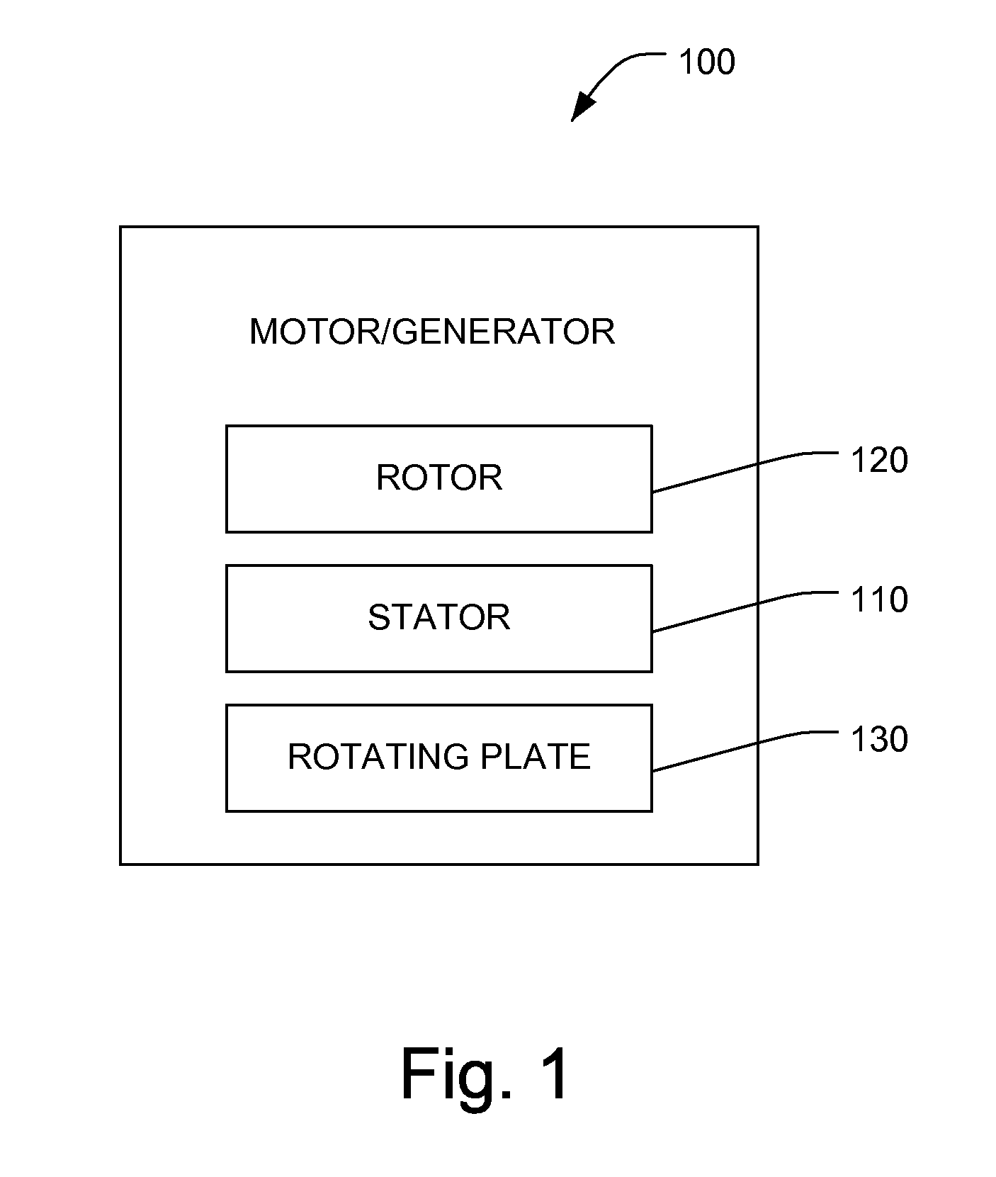
[0020]FIG. 1 illustrates a synchronous machine, such as a motor / generator, 100 in accordance with an aspect of the present invention. The motor / generator 100 includes a stator 110...


PUM


Abstract

The present invention relates to systems and methods for a synchronous motor / generator including at least one back iron element which is rotated along with a rotor of the motor / generator. Rotation of the back iron(s) mitigates eddy current losses and improves efficiency in the motor / generator. The motor / generator also includes at least one stator winding supported in a non-conductive structure attached to the machine frame. The motor / generator of the present invention can also include at least one permanent magnet located in the rotor. The permanent magnet(s) cooperates with rotor windings to generate a DC magnetic field for the rotor. The components of the motor / generator can be configured in an axial gap topology, radial gap topology, or any other suitable topology.

Description

CROSS REFERENCE TO RELATED APPLICATIONS[0001]This application claims the benefit of U.S. patent application Ser. No. 09 / 932,755 filed Aug. 17, 2001 and entitled HYBRID SUPERCONDUCTING MOTOR / GENERATOR, which is a continuation of U.S. patent application Ser. No. 09 / 570,249 filed on May 12, 2000 and entitled HYBRID SUPERCONDUCTING MOTOR / GENERATOR, the entireties of which are incorporated herein by reference.FIELD OF THE INVENTION[0002]The invention described below generally relates to synchronous machines, and more particularly, to systems and methods for rotating a back iron to mitigate losses in synchronous machines.BACKGROUND OF THE INVENTION[0003]Recent advances in superconductivity have led to an increased interest in the development and commercialization of superconducting electromechanical rotating (SER) devices such as large electric generators and large electric motors, including synchronous AC motors. Such devices typically include a superconductive rotor having a vacuum jack...

Claims


Application Information

Patent Timeline
IPC IPC(8): H02K1/22H02K21/04H02K55/04
CPCH02K21/042H02K55/04H02K21/046Y02E40/625Y02E40/60
Inventor DOMBROVSKI, VIATCHESLAV V.
Owner RELIANCE ELECTRIC TECH
Why Eureka
Try Eureka