
Programmable and erasable digital switch device and fabrication method and operating method thereof

a digital switch and erasable technology, applied in semiconductor devices, digital storage, instruments, etc., can solve the problems of only being able to program fuses or anti-fuses once, programming is not reversible, and their application thus is limited, so as to improve the stability and reliability of the programmable and erasable digital switch device of the present invention, the effect of high electron injection efficiency and low current consumption

Active Publication Date: 2007-11-06
POWERCHIP SEMICON MFG CORP
View PDF9 Cites 8 Cited by
  • Summary
  • Abstract
  • Description
  • Claims
  • Application Information

AI Technical Summary

Benefits of technology

The present invention is a programmable and erasable digital switch device that can be easily fabricated and operated using low power. The device includes a substrate, a memory transistor, a common bit line, and a word line. The device can be programmed and erased multiple times using the FN tunneling effect. The device is simple to operate and compatible with traditional memory fabrication methods. The common bit line and word line are electrically short to each other, and the device includes a conductive plug for short-circuiting the first and second doped regions. The device can be programmed using a first and second stacked gate structure, with a first and second inter-gate dielectric layer and tunneling dielectric layer. The device can be used in various applications such as memory and logic devices.

Problems solved by technology

If partial memory blocks in the main memory cell arrays fail and cannot be repaired, fuses are burned out by an electric current or a laser to change the connection among the remaining normal memory cell arrays.
However, either fuses or antifuses can only be programmed once.
It means that the programming is not reversible.
Their applications thus are limited.
These operations may damage other devices.

Method used


Image

  • Programmable and erasable digital switch device and fabrication method and operating method thereof
  • Programmable and erasable digital switch device and fabrication method and operating method thereof
  • Programmable and erasable digital switch device and fabrication method and operating method thereof

Examples


Embodiment Construction

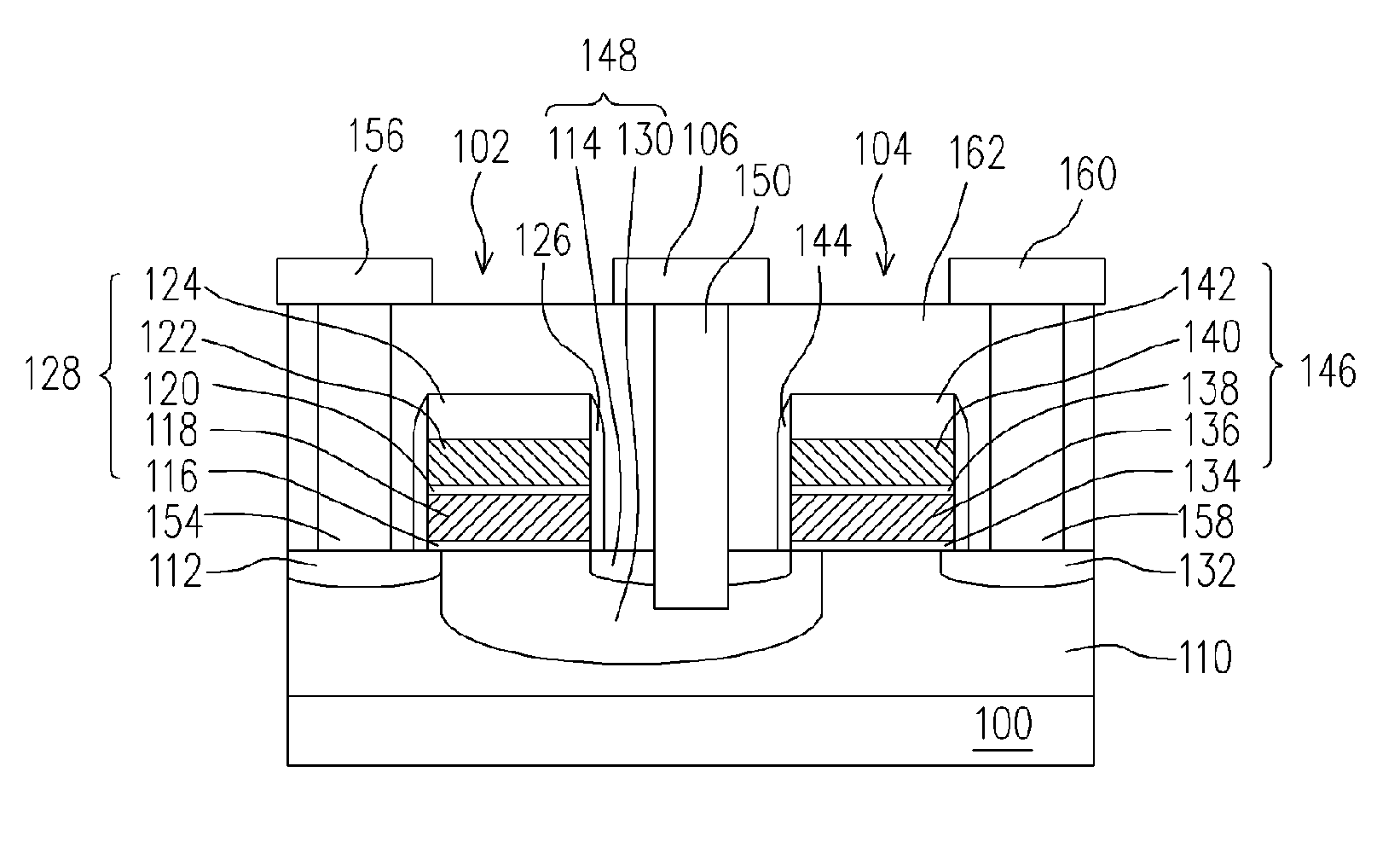
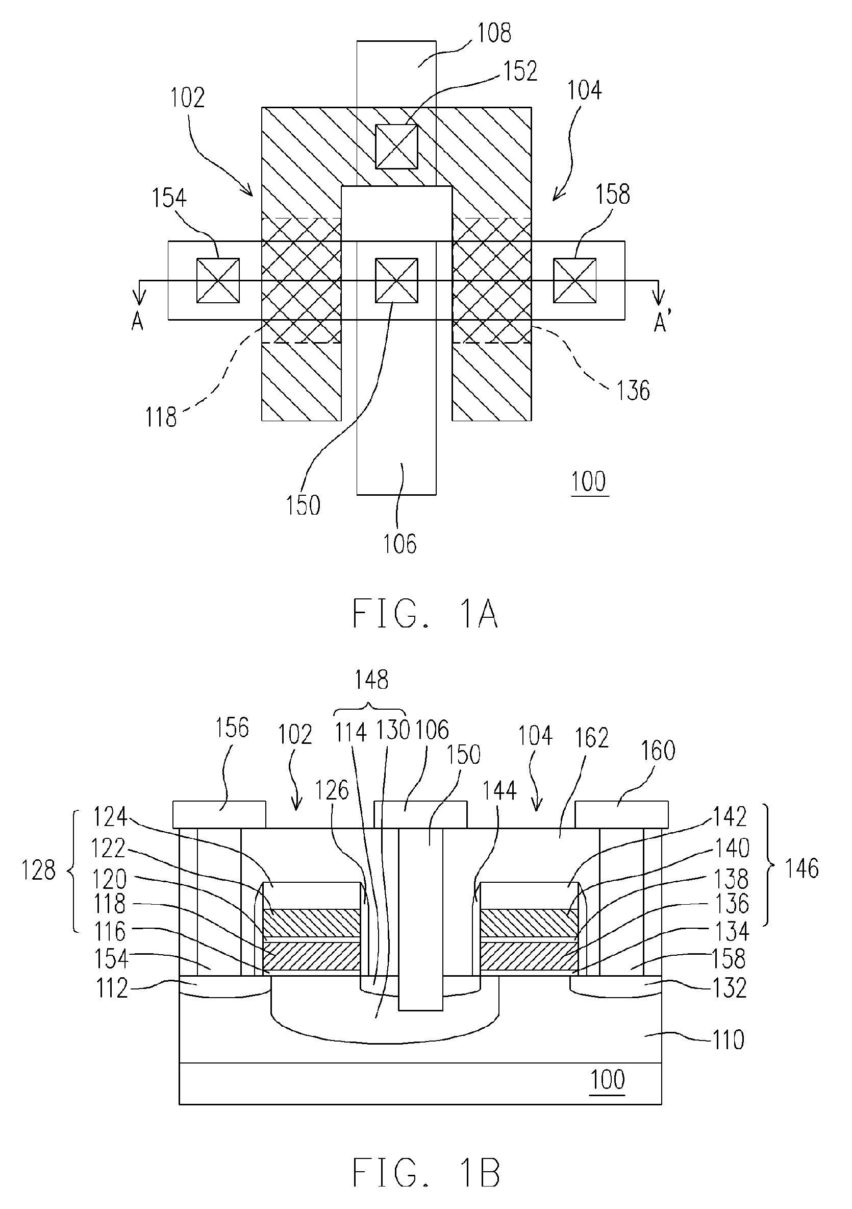
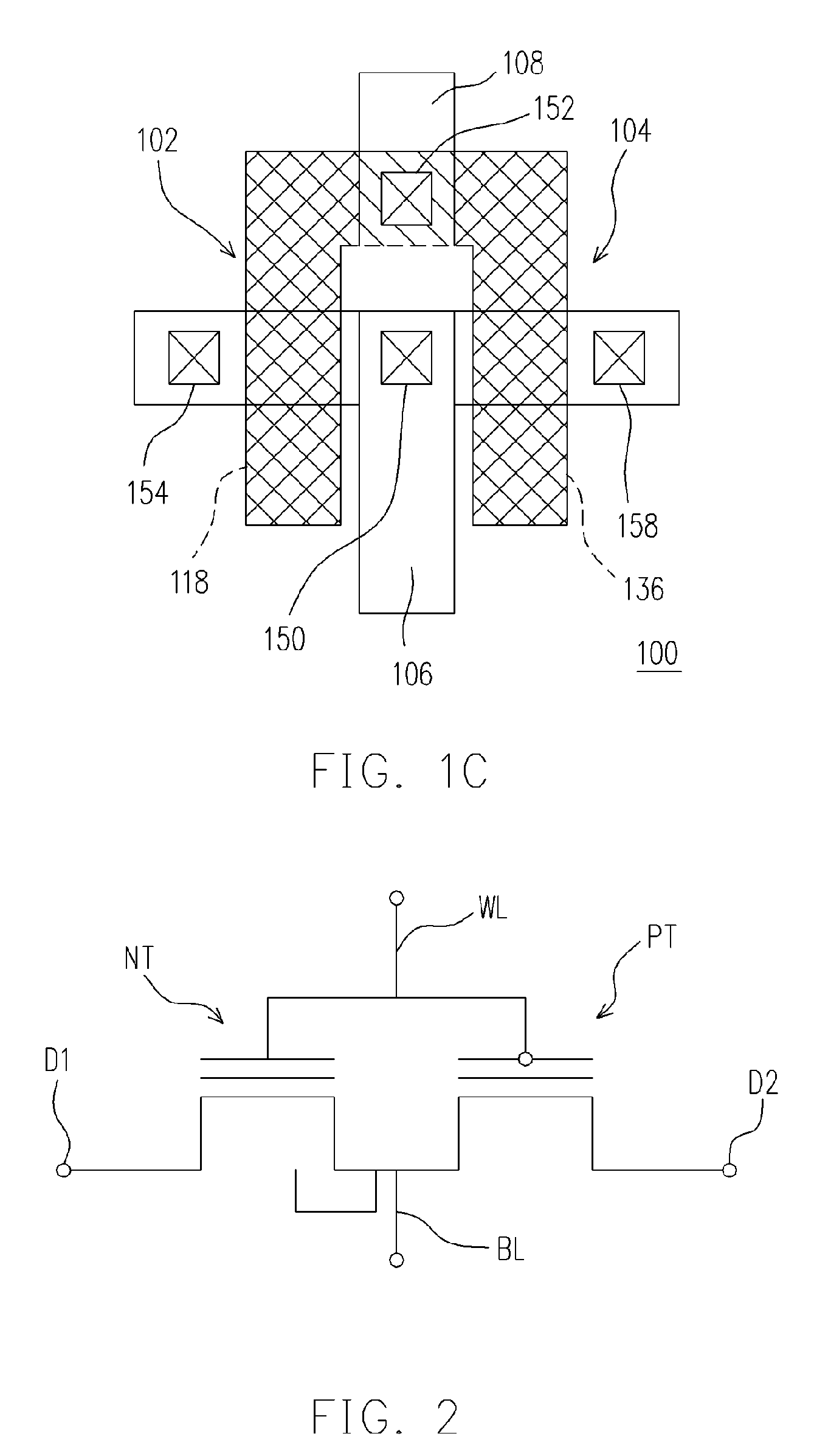
[0054]FIG. 1A is a top view of a programmable and erasable digital switch device according to a preferred embodiment of the present invention. FIG. 1B is a cross sectional view of the structure of FIG. 1A along A-A′. FIG. 1C is a top view of a programmable and erasable digital switch device according to another preferred embodiment of the present invention.

[0055]Referring to FIGS. 1A and 1B, the programmable and erasable digital switch device of the present invention includes, for example, the substrate 100, the N-type memory transistor 102, the P-type memory transistor 104, the common bit line 106 and the word line 108.

[0056]The substrate 100 can be, for example, a silicon substrate. In the embodiment, the N-type well region 110 is formed within the substrate 100, for example.

[0057]The N-type memory transistor 102 is disposed over the substrate 100, for example. The N-type memory transistor 102 includes, for example, the N-type doped region 112, the N-type doped region 114, the tun...


PUM


Abstract

A programmable and erasable digital switch device is provided. An N-type memory transistor and a P-type memory transistor are formed over a substrate. The N-type memory transistor includes a first N-type doped region, a second N-type doped region, a first charge storage layer and a first control gate. The P-type memory transistor includes a first P-type doped region, a second P-type doped region, a second charge storage layer and a second control gate. A common bit line doped region is formed between the N-type memory transistor and the P type memory transistor and electrically connects the first N-type region to the second P-type doped region. A word line electrically connects the first control gate to the second control gate.

Description

CROSS-REFERENCE TO RELATED APPLICATION[0001]This application claims the priority benefit of Taiwan application serial no. 94112347, filed on Apr. 19, 2005. All disclosure of the Taiwan application is incorporated herein by reference.BACKGROUND OF THE INVENTION[0002]1. Field of the Invention[0003]The present invention relates to a semiconductor device, a fabrication method and an operating method thereof, and more particularly, to a programmable and erasable digital switch device, a fabrication method and an operating method thereof.[0004]2. Description of the Related Art[0005]An integrated circuit usually includes programmable devices. These programmable devices control the connection of devices in the circuit. These programmable devices are fuses or antifuses.[0006]Fuses are adapted to connect main memory cell arrays and redundancy memory cell arrays. If partial memory blocks in the main memory cell arrays fail and cannot be repaired, fuses are burned out by an electric current or ...

Claims


Application Information

Patent Timeline
Patent Type & Authority Patents(United States)
IPC IPC(8): H01L21/8247
CPCH01L27/11521H01L27/115H10B69/00H10B41/30
Inventor YANG, CHING-SUNGWONG, WEI-ZHE
Owner POWERCHIP SEMICON MFG CORP
Learn More