
Filamentary pad for improved mist elimination and mass transfer

a technology of mesh pads and filaments, applied in the field of filamentous knitted or woven mesh pads, can solve the problems of complex and expensive construction, inability to make structured mesh pads of ozolins, et al., to be made by the conventional stacked horizontal layer assembly method, and increase the cost and complexity of construction. , to achieve the effect of maximizing gas flow

Inactive Publication Date: 2007-11-06
LERNER BERNARD J
View PDF42 Cites 13 Cited by
  • Summary
  • Abstract
  • Description
  • Claims
  • Application Information

AI Technical Summary

Benefits of technology

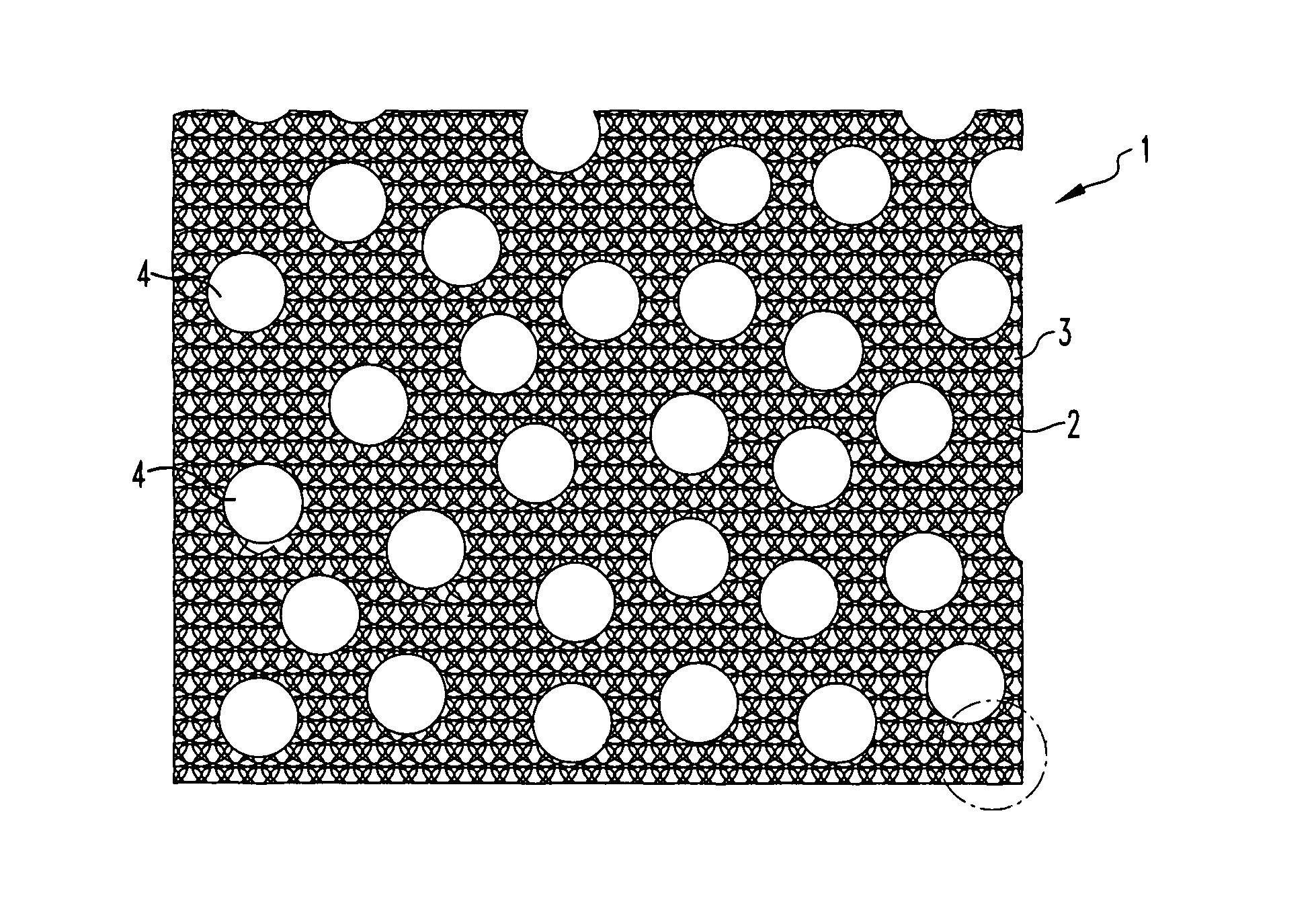
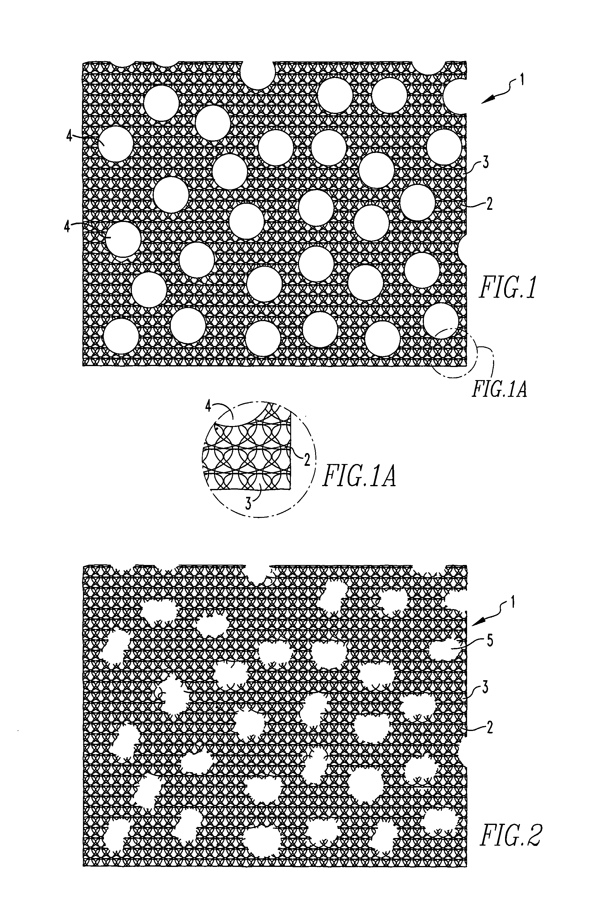
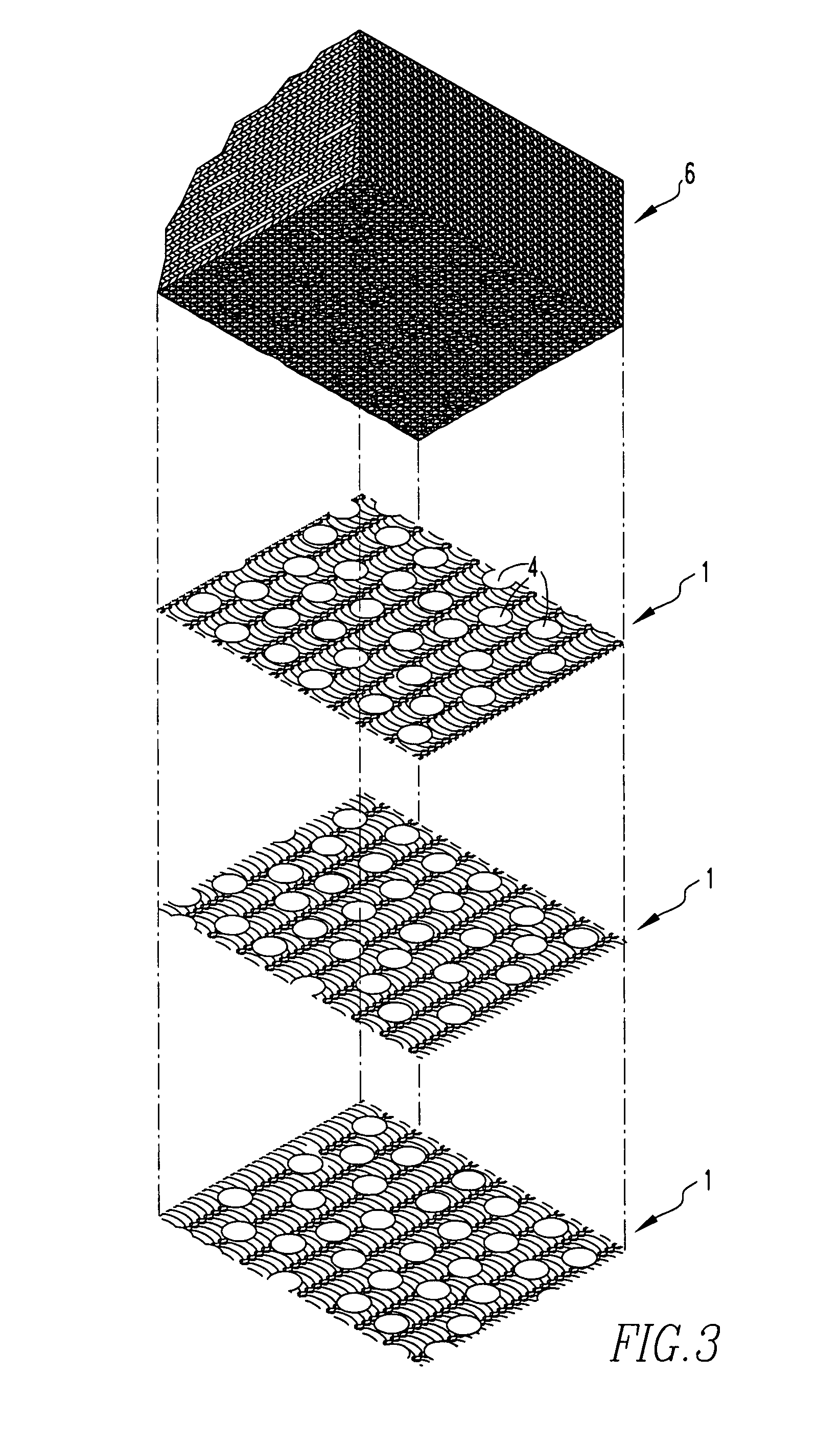
"The present invention provides a simple method and apparatus for maximizing gas flow and liquid loading capacities of filamentary mesh pads used for gas-liquid contacting or mist elimination. The invention involves adding a plurality of layers of mesh with preferential gas flow openings to the pad. These openings provide low-resistance paths for gas flow, allowing for improved gas flow and liquid loading capacities. The layers of mesh are vertically stacked to form the pad, with the preferential gas flow openings occupying between about 10% to 50% of the total area of a layer of mesh. The pad can be woven or knitted and has a graded mesh density, increasing from the bottom to the top of the pad. The method also includes programming a knitting machine or removing needles from a knitting machine to produce a mesh pattern with preferential gas flow openings. Overall, the invention enhances the performance of filamentary mesh pads for gas-liquid contacting and mist elimination applications."

Problems solved by technology

Because entrainment carryover is frequently deleterious to process operation, re-entrainment may be considered as the limiting operating condition for a demisting or mass transfer filamentary pad system.
This competitive counter flow situation impedes liquid drainage flow and typically results in the formation of a liquid layer at the bottom of the pad through which the gas bubbles.
The structured mesh pads of Ozolins, et al., cannot be made by the conventional stacked horizontal layer assembly method.
They are best made by spiral or annular assembly construction methods, which are complicated and expensive to build and are therefore limited to smaller pads sizes.
The drainage roll appendages of Lerner also require additional fabrication steps beyond a conventional layered pad assembly that add to the cost and complexity of construction.

Method used


Image

  • Filamentary pad for improved mist elimination and mass transfer
  • Filamentary pad for improved mist elimination and mass transfer
  • Filamentary pad for improved mist elimination and mass transfer

Examples


Embodiment Construction

[0026]The invention will now be described in detail in relation to a preferred embodiment and implementation thereof that is exemplary in nature and descriptively specific as disclosed. As is customary, it will be understood that no limitation of the scope of the invention is thereby intended. The invention encompasses such alterations and further modifications in the illustrated method and apparatus, and such further applications of the principles of the invention illustrated herein, as would normally occur to persons skilled in the art to which the invention relates.

[0027]As used herein, in the specification and claims, including as used in the examples and unless otherwise expressly specified, all numbers may be read as if prefaced by the word “about”, even if the term does not expressly appear. Also, any numerical range recited herein is intended to include all sub-ranges subsumed therein.

[0028]It has been discovered that the re-entrainment or flooding capacity of a filamentary ...


PUM

PropertyMeasurementUnit
diameteraaaaaaaaaa
densityaaaaaaaaaa
areaaaaaaaaaaa

Abstract

An apparatus and method of making a filamentary pad for improved mist elimination and mass transfer comprising a plurality of layers of mesh, each layer of mesh having a plurality of mesh openings defined therein. A plurality of preferential gas flow openings, each having an area larger than any of the areas of said mesh openings absent said preferential gas flow openings, are defined within at least two layers of mesh. The plurality of layers of mesh are vertically stacked to form the filamentary pad. The preferential gas flow openings provide preferential low-resistance paths for gas flow.

Description

FIELD OF THE INVENTION[0001]This invention relates generally to the field of knitted or woven mesh pads and more particularly relates to the use of filamentary knitted or woven mesh pads used for mist elimination and gas-liquid contact in mass transfer operations.BACKGROUND OF THE INVENTION[0002]Industrial filamentary pads used for inter-phase mass transfer contacting and / or for mist elimination are typically pads that are fabricated of multiple layers of knitted or woven metal or plastic filaments. Industrial woven or knitted-mesh pads are typically made from 4- to 11-mil diameter filaments. For fine drop removal in mist elimination, or for use as liquid-liquid coalescers, composite materials containing 10 to 50 micron diameter fiberglass or plastic filaments co-knitted with a heavier metal or plastic mesh framework are used.[0003]In the manufacture of knitted mesh pads, the knitting machine typically knits a fabric of interlocked wire loops in the form of a continuous tube or cyli...

Claims


Application Information

Patent Timeline
Patent Type & Authority Patents(United States)
IPC IPC(8): B01D46/00
CPCB01D45/08B01D46/003Y10S55/43Y10S264/48Y10S55/05
Inventor LERNER, BERNARD J.
Owner LERNER BERNARD J
Learn More