
Power ring pulse capacitor

a technology of power ring and capacitor, which is applied in the direction of pulse manipulation, pulse technique, electrical apparatus casing/cabinet/drawer, etc., can solve the problems of reducing the energy density of the capacitor, reducing the maximum current that can be carried by the thin metallic coating, and not necessarily connecting elements to the capacitor. , to achieve the effect of low weight, low esl and low esr

Inactive Publication Date: 2007-10-30
SB ELECTRONICS
View PDF7 Cites 11 Cited by
  • Summary
  • Abstract
  • Description
  • Claims
  • Application Information

AI Technical Summary

Benefits of technology

[0015]Another advantage of the present invention is that it has a very low ESL.
[0016]Another advantage of the present invention is that it has a very low ESR.
[0017]Another advantage of the present invention is that the load connected to the capacitor can be placed within the hollow center of the capacitor.
[0018]Another advantage of the present invention is that the capacitor can be formed around an irregularly shaped load or around an irregularly shaped housing that later holds the load.
[0019]Another advantage of the present invention is that no robust housing is required.
[0020]Another advantage of the present invention is that immersion in an insulating medium such as oil is not required.

Problems solved by technology

However, the maximum current that can be carried by the thin metallic coating is limited by thermal damage and ablation of the coating.
However, the extra space required by the foil reduces the energy density of the capacitor.
However, these circuit elements are not necessarily connected to the capacitor.
The capacitor finds utility in DC and low frequency AC applications, but is not suitable for pulsed power applications.

Method used


Image

  • Power ring pulse capacitor
  • Power ring pulse capacitor
  • Power ring pulse capacitor

Examples


Embodiment Construction

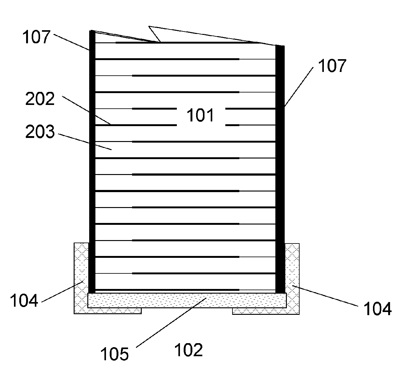
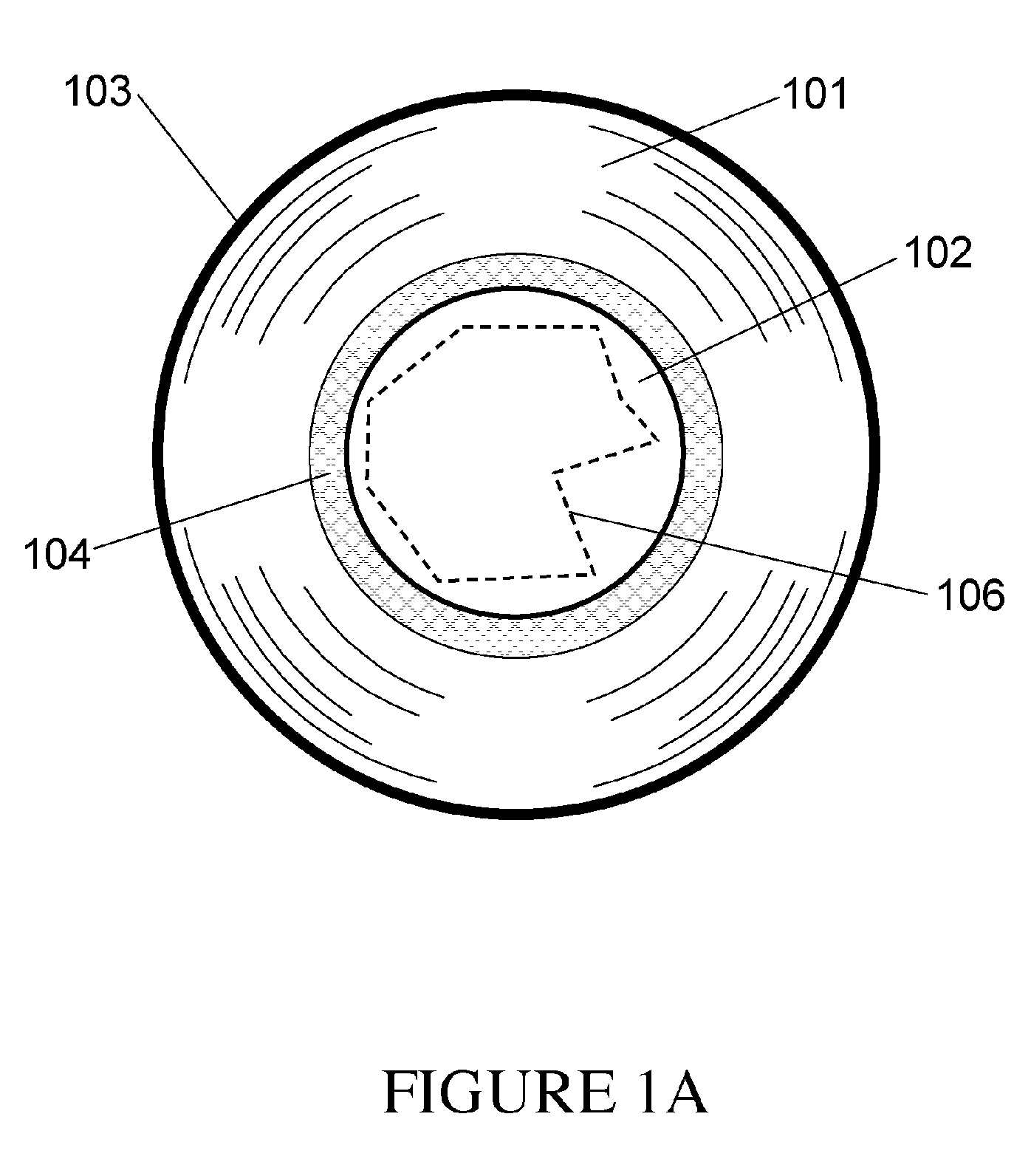
[0036]A metallized film polymeric power ring capacitor is shown in FIG. 1A. The capacitor consists of a body 101 comprised of a plurality of windings of metallized polymeric insulation material. The windings are formed around a central support rod that is later removed, leaving a hollow center 102 of the capacitor. The hollow center 102 is available for locating the electronic load 106 to which the capacitor is connected. The outer diameter of the capacitor is sealed or otherwise fixed using a protective layer 103 such as polymeric resin or insulating tape. The region adjacent to the hollow center supports two electrically conductive flanges 104. Although the FIG. 1A demonstrates a ring capacitor with a circular shape, it is to be understood that a ring capacitor may take on any cross-sectional shape, provided that it forms a simple loop with a closed path. Other examples of capacitor ring shapes include an ellipse, polygon or an irregular smooth curve.

[0037]FIG. 1B is a cross-secti...


PUM


Abstract

A wound, metallized dielectric film capacitor for pulsed power applications is disclosed. The capacitor forms a wound metallized polymer film in the shape of a closed path ring. The electrical load is placed within the inner opening of the capacitor. The capacitor has low inductance and resistance, scales to high energy levels, and can be formed around the electrical load.

Description

[0001]This application claims the priority of U.S. Provisional Application Ser. No. 60 / 578,508 filed Jun. 9, 2004 and entitled “POWER RING PULSE CAPACITOR”, the subject matter of which is incorporated herein by reference.FIELD OF INVENTION[0002]The present invention relates to a multi-layer film capacitor capable of delivering high peak electrical currents and high peak electrical power to an electrical load.DESCRIPTION OF THE PRIOR ART[0003]Capacitors are electrical devices that are capable of storing electrical energy for later use. The rate of energy storage and the rate of energy discharge from a capacitor are dependent on the application. The required energy storage density per volume or the energy storage density per weight is also determined by the application. Pulsed power applications involve the short-term release of electrical energy from a capacitor over time-scales of nanoseconds to milliseconds, and with peak electrical currents of Amperes to Mega-Amperes. For example,...

Claims


Application Information

Patent Timeline
Patent Type & Authority Patents(United States)
IPC IPC(8): H01G4/32H01G9/028H01G9/06H01G9/08H01G9/15H03K5/00
CPCH01G9/028H01G9/151H01G9/08H01G9/06
Inventor HOSKING, TERRY ALAN
Owner SB ELECTRONICS
Learn More