
Image generating method and MRI apparatus

a generation method and image technology, applied in the direction of instruments, reradiation, measurement using nmr, etc., can solve the problems of artifact generation, inability to obtain satisfactory images, and inability to acquire data by the body coil, etc., to achieve excellent picture quality

Active Publication Date: 2007-10-30
GE MEDICAL SYST GLOBAL TECH CO LLC
View PDF17 Cites 11 Cited by
  • Summary
  • Abstract
  • Description
  • Claims
  • Application Information

AI Technical Summary

Benefits of technology

[0009]Therefore, an object of the present invention is to provide an image generating method and an MRI apparatus both capable of generating an MR image excellent in picture quality, based on respective data obtained by n coils.
[0015]In the image generating method according to the third aspect, the sensitivity maps of the respective coils are created based on the partial data in the low frequency region, of the respective data in addition to the ability to suppress sensitivity variations in a manner similar to the image generated from the data obtained by one large coil high in the degree of uniformity. Therefore, it is possible to eliminate the influence of high-frequency noise and obtain a high SNR (Signal to Noise Ratio) similar to the data obtained by the n coils.
[0017]In the image generating method according to the fourth aspect, variations in phase and variations in signal intensity due to cables, pre-amplifiers, receivers and the like from the receiving terminals of the respective coils to data sampling terminals are actually measured. The phase shift amounts and the intensity correction coefficients are determined and stored in advance. The intensities and phases of the respective images are corrected using them upon actual photographing. Therefore, a process at the actual photographing or imaging becomes simple.
[0046]According to the image generating method and MRI apparatus of the present invention, an image high in the degree of uniformity can be generated as compared with the conventional sum-of-square method. The acquisition of data by the use of a body coil becomes unnecessary. As a result, a scan time can be shortened. The present invention resists even an artifact developed depending on the motion of a patient. Further, since the sensitivity of each coil is corrected based on the emulation of the sensitivity of a large coil, a correction to a diseased part as in the correction of an image by image processing is no longer made.

Problems solved by technology

However, a satisfactory image cannot be obtained due to variations in sensitivity of each coil.
The conventional method of correcting the sensitivity, based on the reference image generated from the data obtained using the body coil is accompanied by the problem that the acquisition of data by the body coil is needed in addition to the acquisition of data by the phased array coil.
Also a problem arises in that when a patient moves during the periods of the acquisition of the data by the phased array coil and the acquisition of the data by the body coil, an artifact is generated.
Further, the known method of generating the images from the respective data obtained by the n coils and the sensitivity maps of the respective coils is accompanied by the problem that although the sensitivity maps of the respective coils are required, the acquisition of data by a body coil is required in addition to the acquisition of data by a phased array coil to create the sensitivity maps.

Method used


Image

  • Image generating method and MRI apparatus
  • Image generating method and MRI apparatus
  • Image generating method and MRI apparatus

Examples


embodiment 1

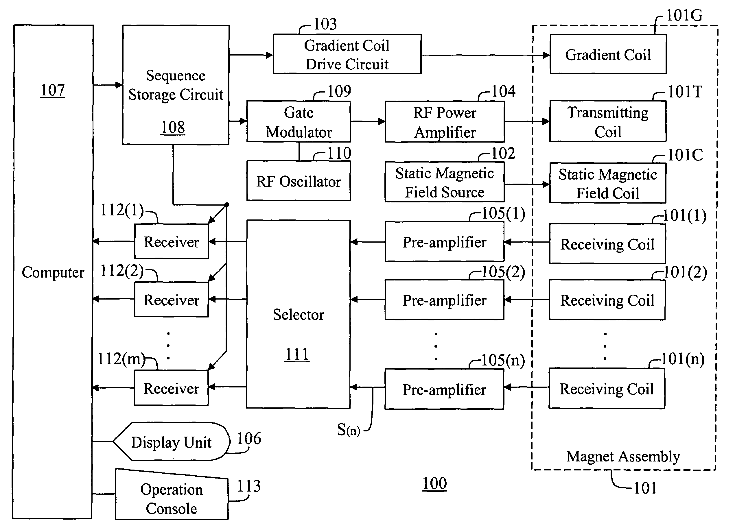
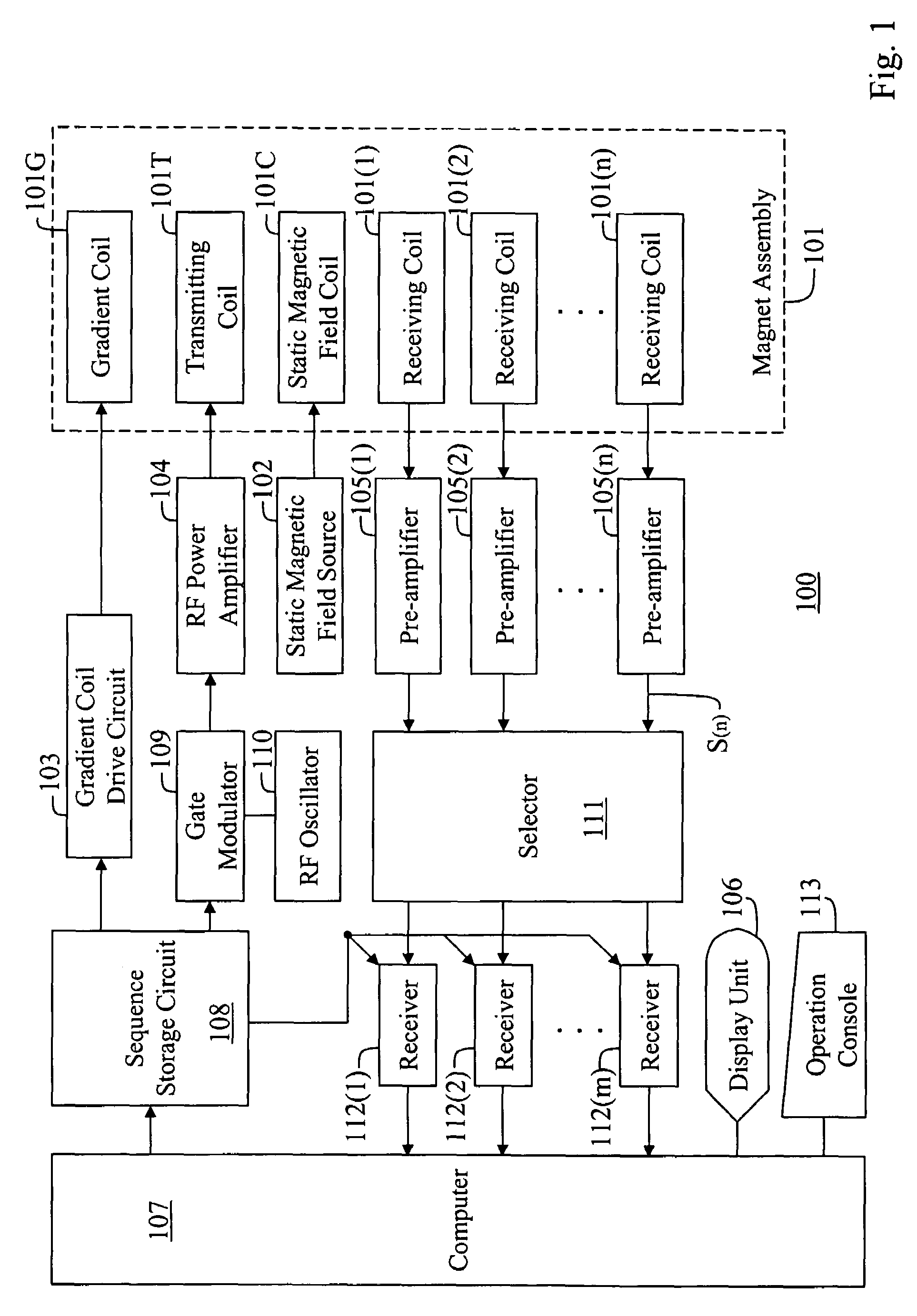
[0065]FIG. 1 is a block diagram showing an MRI apparatus 100 according to an embodiment 1.

[0066]In the MRI apparatus 100, a magnet assembly 101 has a spatial portion (bore) for inserting a sample thereinside. A static magnetic field coil 101C for applying a constant static magnetic field to the sample, a gradient or slope coil 101G for generating gradient or slope magnetic fields for an X axis, a Y axis and a Z axis, a transmitting coil 101T for supplying an RF pulse for exciting the spin of a nucleus in the sample, and n-channel receiving coils 101(1), 101(2), . . . , 101(n) for receiving an NMR signal from the sample are disposed in the magnet assembly 101 so as to surround the spatial portion.

[0067]Incidentally, a slice axis, a phase encode axis and a lead axis are formed by combinations of the X axis, Y axis and Z axis of the gradient coil 101G of the magnet assembly 101.

[0068]The static magnetic field coil 101C, the gradient coil 101G and the transmitting coil 101T are respecti...

embodiment 2

[0093]FIG. 6 is a flow chart showing an imaging / image-generating process according to an embodiment 2.

[0094]In Step T11, a sample is imaged using a first coil 101(1), a second coil 101(2), . . . , an nth coil 101(n), and first data K(1), second data K(2), . . . , nth data K(n) for a k space are read into a computer 107.

[0095]In Step T12, a first low resolution image d(1), a second low resolution image d(2), . . . , an nth low resolution image d(n) are reconstructed from partial data close to k=0 (equivalent to about 32 lines near k=0 in the case of a resolution of 256×256, for example), of the first data K(1), second data K(2), . . . , nth data K(n). Incidentally, these images are complex images, and their pixel values are equivalent to vectors and have phases and magnitude.

[0096]In Step T13, a coil number counter is initially set to k=2.

[0097]In Step T14, the respective pixel values of a kth low resolution image d(k) are phase / amplitude-corrected using a kth phase shift amount φ(k)...

embodiment 3

[0112]FIG. 7 is a flow chart showing a calibrating process according to an embodiment 3.

[0113]In Step S11, an operator positions and images or photographs a first coil 101(1), second coil 101(2), . . . , nth coil 101(n) and a phantom, and reads first data K(1), second data K2), . . . , nth data K(n) of a k space into a computer 107.

[0114]In Step S12, a first low resolution image d(1), a second low resolution image d(2), . . . , nth low resolution image d(n) are reconstructed from partial data close to k=0 (equivalent to about 32 lines near k=0 in the case of a resolution of 256×256, for example), of the first data K(1), second data K(2), . . . , nth data K(n). Incidentally, these images are complex images, and their pixel values are equivalent to vectors and have phases and magnitude.

[0115]In Step S13, a coil number counter is initially set to k=2.

[0116]In Step S14, a composite signal (vector obtained by adding vectors of respective pixels) of a pixel group (about 30×30 pixels in th...


PUM


Abstract

A method of generating an MR image based on respective data obtained by n (≧2) coils, respective low resolution images are generated using partial data in a low frequency region for the data obtained by the n coils. The intensities and phases of the low resolution images are corrected. The post-correction images are added together to generate one composite low resolution image. Sensitivity maps of the respective coils are created from the composite low resolution image and the respective low resolution images. One image is generated from the respective data and the respective sensitivity maps.

Description

CROSS REFERENCE TO RELATED APPLICATIONS[0001]This application claims the benefit of Japanese Application No. 2004-128008 filed Apr. 23, 2004 and Japanese Application No. 2004-144350 filed May 14, 2004.BACKGROUND OF THE INVENTION[0002]The present invention relates to an image generating method and an MRI (Magnetic Resonance Imaging) apparatus, and more specifically to an image generating method and an MRI apparatus capable of generating an MR image excellent in image quality, based on respective data obtained by n (≧2) coils.[0003]One MR image has heretofore been generated by a sum of square method based on respective data obtained by coils of a phased array coil. However, a satisfactory image cannot be obtained due to variations in sensitivity of each coil. Therefore, there has been proposed a method of acquiring data by a body coil having uniform sensitivity to thereby create a reference image, and correcting the sensitivity of each coil using the reference image (refer to, for exa...

Claims


Application Information

Patent Timeline
Patent Type & Authority Patents(United States)
IPC IPC(8): G01V3/00A61B5/055G01R33/3415G01R33/48G01R33/56G03B42/00
CPCG01R33/3415
Inventor NABETANI, AKIRA
Owner GE MEDICAL SYST GLOBAL TECH CO LLC
Learn More