
Method of producing a sputtering target

a target and target technology, applied in the field of sputtering targets, can solve the problems of insufficient laser power required for recording and erasing, the above-mentioned conventional phase-change optical recording media cannot meet all the requirements of phase-change rewritable optical recording medium requirements, and the difficulty of overwriting, etc., to achieve the effect of improving the c/n ratio, erasability, and repeatability

Inactive Publication Date: 2007-10-30
RICOH KK
View PDF32 Cites 8 Cited by
  • Summary
  • Abstract
  • Description
  • Claims
  • Application Information

AI Technical Summary

Benefits of technology

[0020]Accordingly, a first object of the present invention is to provide a sputtering target for fabricating a recording layer of an optical recording medium with improved C / N ratio, erasability, recording sensitivity, and repetition properties.
[0022]A third object of the present invention is to provide an optical recording medium with improved C / N ratio, erasability, recording sensitivity, and repetition properties.

Problems solved by technology

This kind of phase-change optical information recording medium enables the overwriting of information by the application of a single laser beam thereto, although such overwriting is difficult to conduct by the application of a single laser beam in magneto-optical memory using a magneto-optical recording medium.
However, none of the above-mentioned conventional phase-change optical recording media satisfies all the requirements for the phase-change rewritable optical recording medium.
However, this optical information recording medium has the shortcomings that the erasability is low and the laser power required for recording and erasing cannot be sufficiently reduced.
However, this reference does not show any specific erasability obtained at the overwriting operation, and according to the experiments conducted by the inventors of the present invention, the erasability in the course of the overwriting operation is unsatisfactory and the recording sensitivity is insufficient for use in practice.
The sensitivity and erasability required for the recording medium cannot be satisfied in any of the above-mentioned conventional optical recording media.
However, there are still some problems remaining unsolved in those conventional optical recording media.
However, if the user does not succeed in writing the data in the CD-R, the CD-R becomes unavailable because it is impossible to correct the data.
A rewritable compact disk has been researched and developed by utilizing the magneto-optical recording medium, but the compact disk thus obtained has the shortcomings that there is difficulty in satisfactorily carrying out the overwriting operation, and the compatibility with the CD-ROM or CD-R is poor.
However, none of the rewritable compact disks reported in the aforementioned references is satisfactory with respect to the overall performance, such as the compatibility with CD-R, recording and erasing performance, recording sensitivity, maximum number of repeated overwriting operations, maximum number of repeated reproducing operations, and shelf stability.
Those drawbacks are mainly ascribed to low erasability due to the composition and configuration of a recording material employed in each compact disk.

Method used

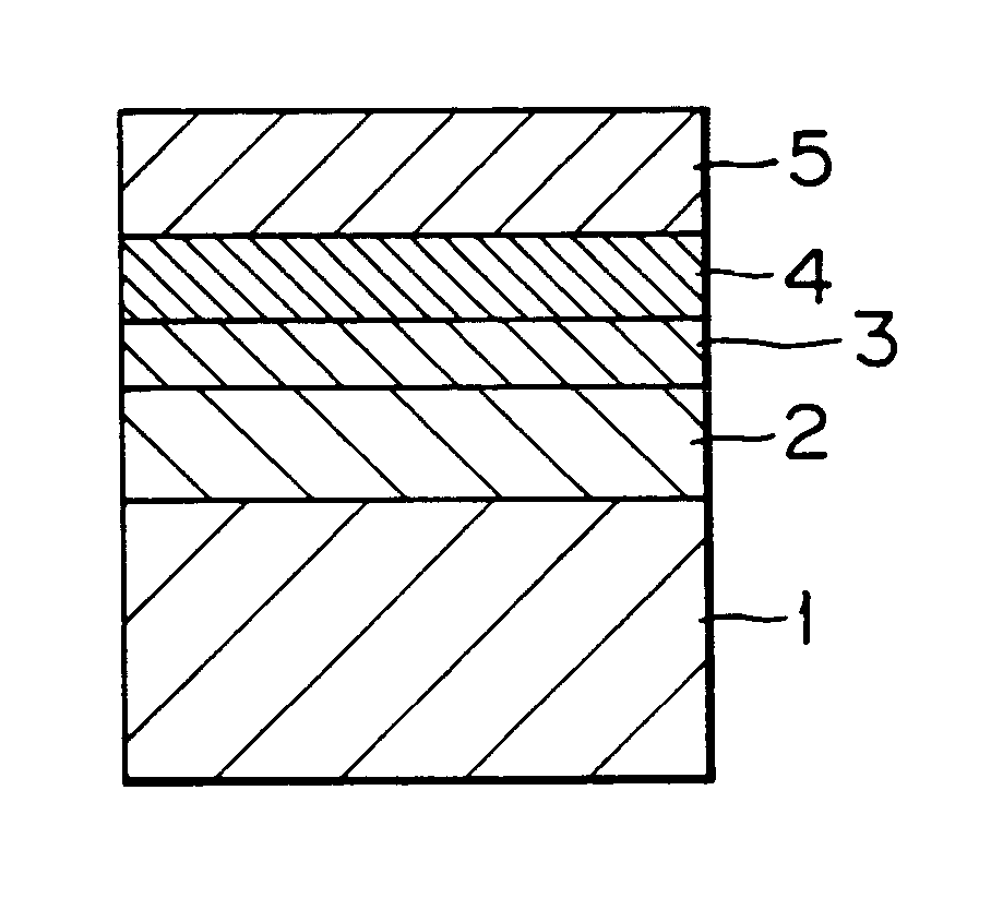
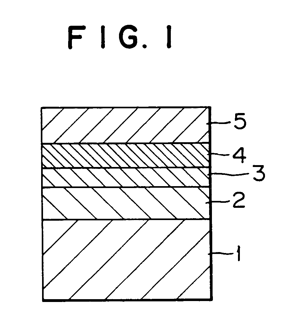
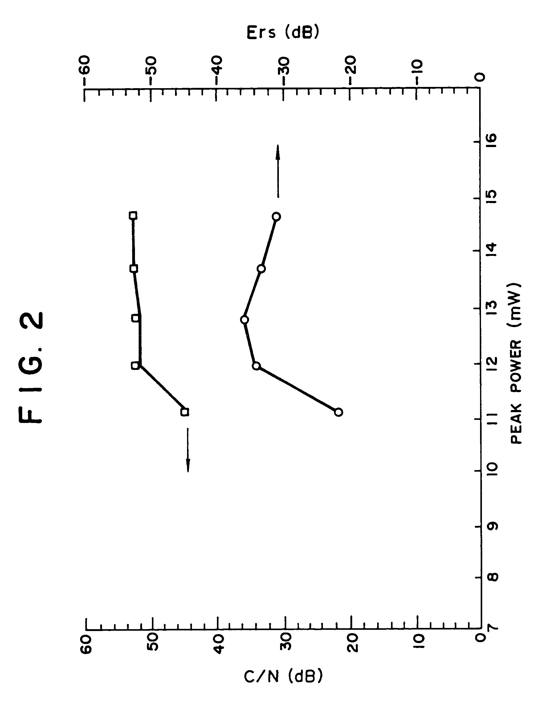

Image

  • Method of producing a sputtering target
  • Method of producing a sputtering target
  • Method of producing a sputtering target

Examples


example 9

[0129]The procedure for fabricating the disk-shaped optical recording medium No. 5 in Example 5 was repeated except that the method of producing the target for fabricating the recording layer of the recording medium No. 5 in Example 5 did not include the heat treatment step prior to the sintering step. Thus, a disk-shaped optical recording medium No. 9 according to the present invention was fabricated.

[0130]The overwriting characteristics of the optical recording medium No. 9 were evaluated at a linear speed of 5 m / sec in the same manner as in Example 5.

[0131]FIG. 3 is a graph which shows the overwriting characteristics of the optical recording medium No. 9.

[0132]In comparison with the graph of FIG. 3, the optical recording medium No. 5 is superior to the recording medium No. 9 with respect to the disk characteristics, such as the C / N ratio and the erasability, and the overwriting sensitivity.

examples 10 to 12

[0133]The procedure for fabricating the disk-shaped optical recording medium No. 3 in Example 3 was repeated except that nitrogen gas was contained in the atmosphere with concentrations of 3.0, 6.0, and 10.0 mol %, respectively in Example 10, Example 11, and Example 12 when the recording layer was formed on the first heat-resistant protective layer by sputtering.

[0134]Thus, disk-shaped optical recording media Nos. 10 to 12 according to the present invention were fabricated.

[0135]Table 2 shows the composition of each of the thus obtained recording layers in terms of the atomic percents of constituent elements.

[0136]In the same manner as in Example 1, each of the optical recording media Nos. 3, 10, 11 and 12 according to the present invention was repeatedly subjected to the overwriting operation, and the maximum number of the repeated overwriting operations was obtained.

[0137]The results are also shown in Table 2.

[0138]

TABLE 2MaximumNumber ofComposition ofOptimalRepeatedN2 / Recording L...

example 13

[0143]It was confirmed that each of the sputtering targets employed in Examples 1 to 8 for fabricating each recording layer comprises AgInTe2 crystallites with a particle size of 450 Å or less.

[0144]The procedure for fabricating the disk-shaped optical recording medium No. 2 in Example 2 was repeated except that the target for fabricating the recording layer of the recording medium No. 2 in Example 2 was replaced by a target with the same composition as that of the target employed in Example 2, with the particle size of the AgInTe2 crystallites for use in the target material being controlled to 500 Å.

[0145]Thus, a disk-shaped optical recording medium No. 13 according to the present invention was fabricated.

[0146]The overwriting characteristics of the optical recording medium No. 13 were compared with those of the optical recording medium No. 2 by carrying out the overwriting operation at a disk rotation speed of 2 m / s.

[0147]FIG. 4 is a graph which shows the overwriting characteristi...


PUM

PropertyMeasurementUnit
speedaaaaaaaaaa
temperatureaaaaaaaaaa
widthaaaaaaaaaa

Abstract

A sputtering target contains a target material including as constituent elements Ag, In, Te and Sb with the respective atomic percents (atom. %) of α, β, γ and δ thereof being in the relationship of 0.5≦α<8, 5≦γ≦23, 17≦γ≦38, 32≦δ≦73, α≦γ, and α+β+γ+δ=100, and a method of producing the above sputtering target is provided.

Description

CROSS REFERENCE TO RELATED APPLICATIONS[0001]This application is a continuation of application Ser. No. 09 / 956,637 filed Sep. 19, 2001, (now U.S. Pat. No. 6,652,806), which is a division of application Ser. No. 08 / 979,293 filed Nov. 26, 1997 (now U.S. Pat. No. 6,319,368), which is a division of application Ser. No. 08 / 622,681 filed Mar. 26, 1996 (now U.S. Pat. No. 5,736,657).BACKGROUND OF THE INVENTION[0002]1. Field of the Invention[0003]The present invention relates to a sputtering target for fabricating a recording layer of an optical recording medium; a method of producing the sputtering target; a phase-change optical recording medium comprising a recording material in a recording layer thereof, which recording material is capable of causing changes in the phase thereof by the application of a light beam thereto, thereby recording, reproducing and overwriting information therein; a method of forming the recording layer for the above-mentioned phase-change optical recording medium...

Claims


Application Information

Patent Timeline
Patent Type & Authority Patents(United States)
IPC IPC(8): B22F1/00C23C14/06C23C14/34G11B7/0045G11B7/24G11B7/243G11B7/257G11B7/258G11B7/26
CPCC23C14/0623C23C14/3414G11B7/00454G11B7/24G11B7/243G11B7/257G11B7/26C23C14/06B22F2998/10Y10T428/115G11B7/2542G11B7/258G11B7/2585G11B2007/24308G11B2007/2431G11B2007/24314G11B2007/24316B22F9/04B22F1/0003B22F3/10B22F1/09
Inventor IDE, YUKIOIWASAKI, HIROKOKAGEYAMA, YOSHIYUKIKANEKO, YUJIROYAMADA, KATSUYUKISHINOTSUKA, MICHIAKIHARIGAYA, MAKOTODEGUCHI, HIROSHI
Owner RICOH KK
Learn More