
Instrumenting a software application that includes distributed object technology

Active Publication Date: 2007-10-23
MARQETA
View PDF5 Cites 11 Cited by
  • Summary
  • Abstract
  • Description
  • Claims
  • Application Information

AI Technical Summary

Benefits of technology

[0011]A method for instrumenting a compiled software application that includes distributed object technology. The method includes deriving an interface and class of an object of the compiled software application. Additionally, the interface is reconstructed to enable a client to communica

Problems solved by technology

However, there are obstacles associated with measuring the completion time of each distributed object of a software transaction.
For example, one of the obstacles is that the source code of a software application may not be available to the company and / or individual trying to evaluate the performance of the application objects.
Alternatively, the software application itself provides no support for being instrumented.
In this case, proxies being used to intercept the communication between distributed objects usually involves another computer program and increases the communication overhead.
However, there are disadvantages associated with both proxy object solutions.
For example, one of the disadvantages associated with the first solution is that most applications do not support this approach.
Hence, this first solution typically cannot be used with most applications.
Another disadvantage associated with the first solution is that it usually involves coming up with a different solution for each application since each application commonly provides a different programmer's interface, e.g., API (application programming interface).
One of the disadvantages associated with the second solution is that it involves another computer program that intercepts the communication and forwards it to the subsequent object.
Therefore, it introduces one more level of processing thereby adversely affecting the accuracy of the time measurements.
Another disadvantage associated with the second solution is that the protocol used by the client and server to exchange messages usually needs to be well understood by those desiring to measure the performance of the software application.
Otherwise, it can be very difficult to implement the proxy object solution.

Method used


Image

  • Instrumenting a software application that includes distributed object technology
  • Instrumenting a software application that includes distributed object technology
  • Instrumenting a software application that includes distributed object technology

Examples


Embodiment Construction

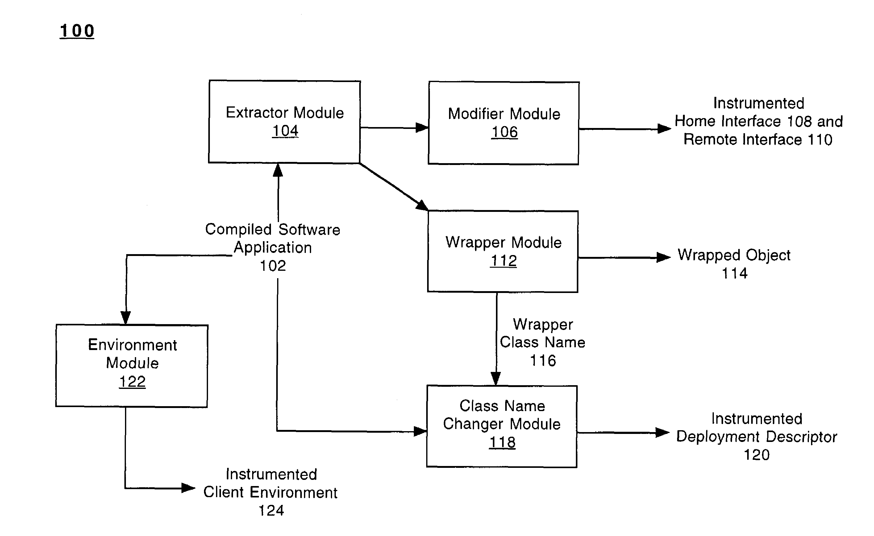
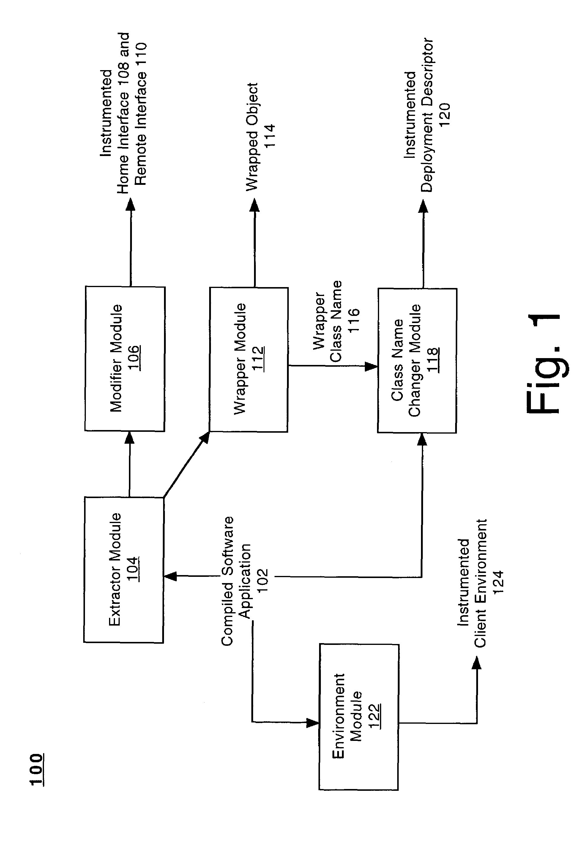
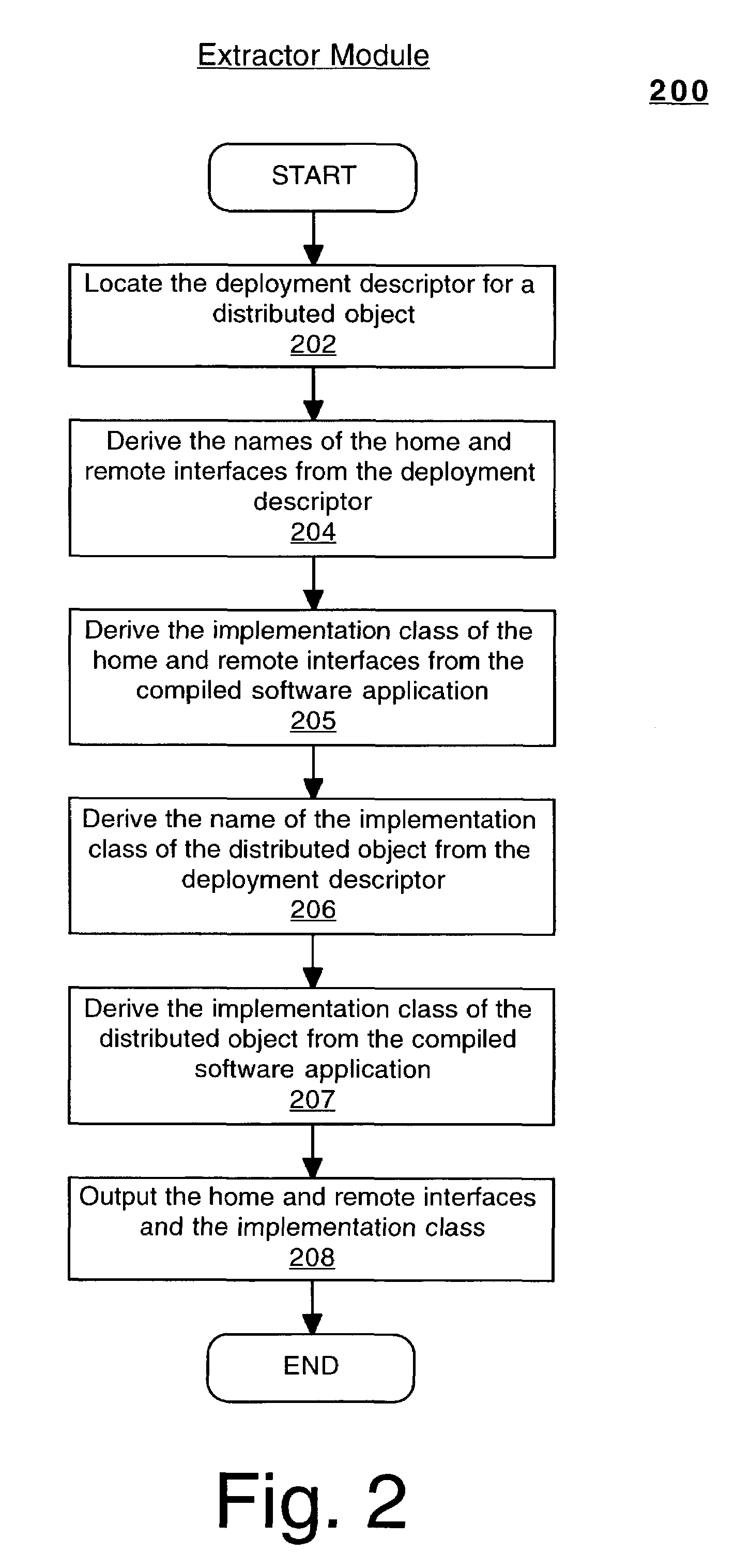
[0021]FIG. 1 is a block diagram of an automated dynamic interface adaptation system 100 in accordance with an embodiment of the present invention for implementing management instrumentation within compiled software applications (e.g., 102) that include distributed object technology. For example, the automated dynamic interface adaptation system 100 may be utilized with distributed object technologies such as, but is not limited to, the Microsoft®.NET programming language and the Java™ 2 Platform, Enterprise Edition (J2EE™) developed by Sun Microsystems. The management instrumentation implemented by the automated dynamic interface adaptation system 100 may be utilized for, but is not limited to, measuring the amount of time spent by a distributed object during a transaction of the compiled software application (e.g., 102). In one embodiment, the automated dynamic interface adaptation system 100 may be a software system implemented in a computer system. Alternatively, the automated dy...


PUM


Abstract

A method for instrumenting a compiled software application that includes distributed object technology. The method includes deriving an interface and class of an object of the compiled software application. Additionally, the interface is reconstructed to enable a client to communicate with the object once the object includes an instrumented function to measure the performance of the object. Furthermore, the object is implemented with the instrumented function. The compiled software application is enabled to utilize the object that includes the instrumented function.

Description

BACKGROUND ART[0001]Computers have become integral tools used in a wide variety of different applications, such as in finance and commercial transactions, computer-aided design and manufacturing, health care, telecommunication, education, etc. Computers are finding new applications as a result of advances in hardware technology and rapid development in software technology. Furthermore, the functionality of a computer system is dramatically enhanced by coupling these types of stand-alone devices together in order to form a networking environment. Within a networking environment, users may readily exchange files, share information stored on a common database, pool resources, and communicate via electronic mail (e-mail) and video teleconferencing. Furthermore, computers which are coupled to a networking environment like the Internet provide their users access to data and information from all over the world.[0002]The software applications that operate on computer systems may be implemen...

Claims


Application Information

Patent Timeline
IPC IPC(8): G06F9/44G06F9/46G06F11/36
CPCG06F9/541G06F11/3466G06F11/3419G06F2201/87G06F2201/865
Inventor GSCHWIND, THOMASGARG, PANKAJ
Owner MARQETA
Learn More