
Optical external cavities having brewster angle wedges

a technology of optical external cavity and wedge, which is applied in the field of optical and spectroscopy, can solve the problems of limiting several key applications of diode lasers, limiting the number of diode lasers in use, and the diode laser system has disadvantages relative to gas and other solid-state lasers. achieve the effect of reducing the size of external laser cavities, high efficiency and high efficiency

Inactive Publication Date: 2007-10-23
CHROMX OPTICS LLC
View PDF31 Cites 5 Cited by
  • Summary
  • Abstract
  • Description
  • Claims
  • Application Information

AI Technical Summary

Benefits of technology

[0025]In prior art designs the Fabry-Perot cavity needs additional optical components to separate the closely spaced interference orders and their corresponding laser modes. The high dispersion Brewster wedges will provide the means to separate these orders with high efficiency and reduce the size of external laser cavities by a factor of two or more. Only such a high dispersion wedge will spatially separate these overlapping modes of a Fabry-Perot filter cavity with the high (over 90%) efficiencies that are highly desirable in a multi-pass laser cavity. The wedges will enable users to spatially separate different Fabry-Perot orders in external cavities at much lower costs than the PDH design. At the same time, the Brewster angle wedges will make possible a significant increase in cavity efficiency. With some custom coatings these efficiencies may approach 90% of the laser beam intensity per pass, dramatically reducing the stray light that propagates inside the cavity.
[0026]If multiple modes of the Fabry-Perot are sufficiently dispersed by the Brewster angle wedge, this component may be used without the piezoelectric feedback to isolate wavelength bands that are more than 100,000 times smaller than the wavelength itself. Thus it is possible to combine the resolution advantage of the PDH cavity with the lower costs of the Littman Metcalf cavity by fabricating a solid, fixed Fabry-Perot cavity in tandem with a high dispersion wedge. Prototypes of such a system have been fabricated and tested in our laboratory in Irvine, Calif. (The solid Fabry-Perot cavities are now available from CVI Laser Corporation. The high dispersion wedges were initially made according to the design requirements of PHI by Janos Technologies but now are also available from II-VI Corporation.)

Problems solved by technology

The diode laser share of this market has remained stagnant at about 33% during the past four years, due in part to the high complexity of current pivot mirrors that control the laser cavities.
The associated fabrication costs limit several key applications of these lasers.
Current diode laser systems do have disadvantages relative to gas and other solid-state lasers.
If these lasers are not controlled by external cavities, they will unpredictably change their output wavelength.
Shifts in these modes occur randomly and are also induced by temperature or voltage drifts, resulting in changes in the spectrum of the output beam.
There are many other examples of earlier patents using several types of prisms besides those referenced here, but all lack certain capabilities.
For example, they all employ a classical prism and are thus expensive to mount and adjust.
Present Littman Metcalf designs require very complex pivot motion control.
They also have lower spectral resolution and efficiency than the Brewster angle wedge designs claimed in this provisional patent.
The fabrication cost of high quality external cavities is now higher than the laser diode that is to be controlled.
The least expensive biochemical fluorescent systems cost just a little over $50,000, and these do not employ stabilized cavity lasers.
This dispersion parameter limits the accuracy and sensitivity of the wavelength tuning.
The three major disadvantages of operating the grating at high angles of incidence to achieve high resolution are as follows.
Such scattered light not only results in beam energy loss, but it contaminates the spectral and spatial purity of the laser beam controlled by this type of cavity.
This particular light loss factor is due to the geometric shadow created by the tilt of the grooves (blaze) relative to the incident angle of the laser beam.
Laser beam losses at the grating contribute to laser mode hop instability.
In the Littman Metcalf cavities this instability occurs near the limits of the cavity wavelength tuning range, where internal cavity light production also declines.
All of the above factors reduce grating performance efficiency and restrict the tuning range for diode laser systems.
Such cavities do have their own disadvantages because interferometers have multiple orders that overlap at the same optical angle.
The PDH cavity control system is more expensive than Littman Metcalf and is one reason the PDH system has not yet become as popular a commercial solution as the grating cavities.
Another reason is that both the phase modulator and the photo-detector with beam splitter both remove light from the beam, reducing cavity efficiency.
These losses also contribute to mode hop instability at the limits of the tuning range just as occurs in the Littman Metcalf system.

Method used


Image

  • Optical external cavities having brewster angle wedges
  • Optical external cavities having brewster angle wedges

Examples


Embodiment Construction

[0028]

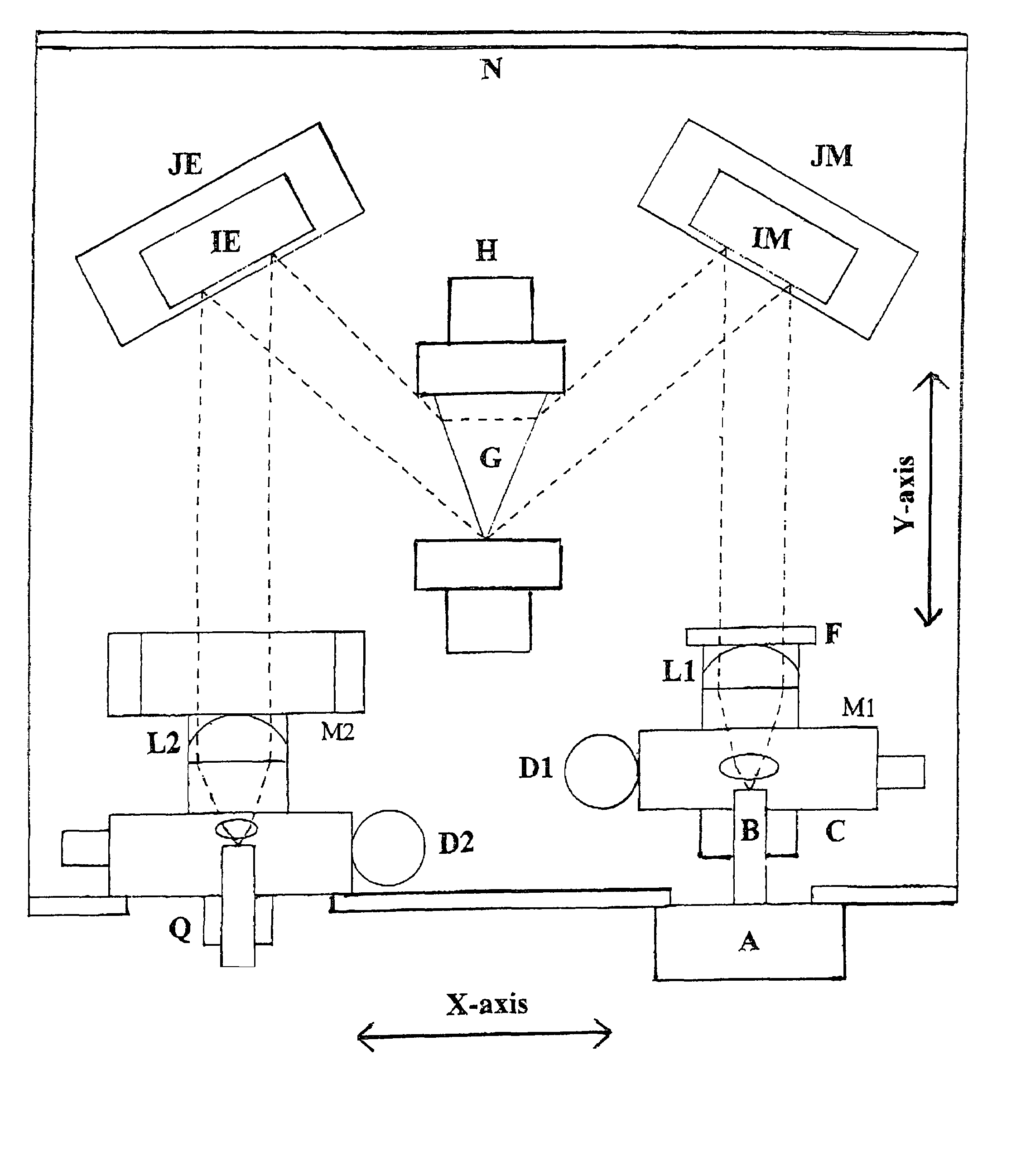
TABLE IDescription of Optical Components Labeled on FIG. 1Optical Component, VendorDescription of FunctionA. Source & Sample cuvetteExcitation source, sample analyte, holderand holder World PrecisionAssembly permits fluorescence to escape.Instruments Coherent LaserB. Optional input fiber, ThorConnects Sample and collimator.LabsC. Mount of input fiber,Holds fiber assembly to lens mounting.Opto SigmaD1. Mounting tube for lensHolds collimator lens on Mounting M1.L1 Opto SigmaD2. Mounting tube for lensHolds camera lens on mounting M2.L2 Opto SigmaF. Fabry-Perot or FB etalonIsolates fluorescent light spatially andfilter CVI Laserspectrally at thirty times that of the wedge.G. The semiconductor wedgeDisperses fluorescence by 1 pixel / 10 cm-1Two-Six CorporationSeparates Fabry-Perot & Echelle Orders.H. Three axis rotation mountAdjusts incident angle of dispersedfor The Two-Six Wedge,spectrum Controls amount of spectralpart G. Opto Sigmadispersion Separates Echelle ordersby cross disper...


PUM


Abstract

This invention consists of an optical external cavity having specialized Brewster angle wedges. The external cavity apparatus utilizes several types of very high index of refraction wedges made from semiconductor and special glass materials. The apparatus limits the oscillation of the optical wavelength modes emitted by a diode laser. In addition, such cavities also simplify the motions of the moveable mirror that returns these selected laser photons to the cavity input beam path or fiber. The wedge also disperses the laser light to isolate the desired wavelength band better than the currently used grating systems. Wavelengths other than the desired wavelength band are dispersed, then reflected at angle away from the return fiber and thus not returned to the amplification cavity inside the laser. The apparatus then emits only the laser photon mode desired by the user.

Description

PRIORITY CLAIM[0001]This application claims priority to U.S. Provisional Application 60 / 509,463 filed on 8 Oct. 2003.FIELD OF THE INVENTIONS[0002]The inventions described below relate the field of optics and spectroscopy, and specifically to optical external cavities used to control laser light.BACKGROUND OF THE INVENTIONS[0003]There is an urgent need to improve the performance of diode laser systems. The overall commercial laser market has expanded from $4B in 1998 to about $6B in 2002. The diode laser share of this market has remained stagnant at about 33% during the past four years, due in part to the high complexity of current pivot mirrors that control the laser cavities. The associated fabrication costs limit several key applications of these lasers. Despite these limitations, financial investment in the diode share of the laser market remains surprisingly strong. Private investment in novel optical components has only declined from $1.8B to $1.1B during the past year. During ...

Claims


Application Information

Patent Timeline
IPC IPC(8): H01S3/13
CPCH01S5/141H01S5/4087H01S5/146
Inventor FAY, JR., THEODORE DENIS
Owner CHROMX OPTICS LLC
Learn More