
Circuit and method for startup of a band-gap reference circuit

a reference circuit and band-gap technology, applied in the field of electromechanical circuits, can solve the problems of multiple output voltages of the band-gap reference circuit that it can become trapped, and the output current of the band-gap reference circuit can vary with process, voltage and temperature (pvt),

Active Publication Date: 2007-10-23
GULA CONSULTING LLC
View PDF17 Cites 41 Cited by
  • Summary
  • Abstract
  • Description
  • Claims
  • Application Information

AI Technical Summary

Benefits of technology

[0016]The circuit portion for comparing may include a comparator with or without hysteresis. In one example, the startup current is selectively activated if the band-gap voltage output is less than the startup reference signal, and selectively deactivated if the band-gap voltage output is greater than the startup reference signal.
[0017]According to another broad aspect of another embodiment of the present invention, disclosed herein is a band-gap reference circuit including

Problems solved by technology

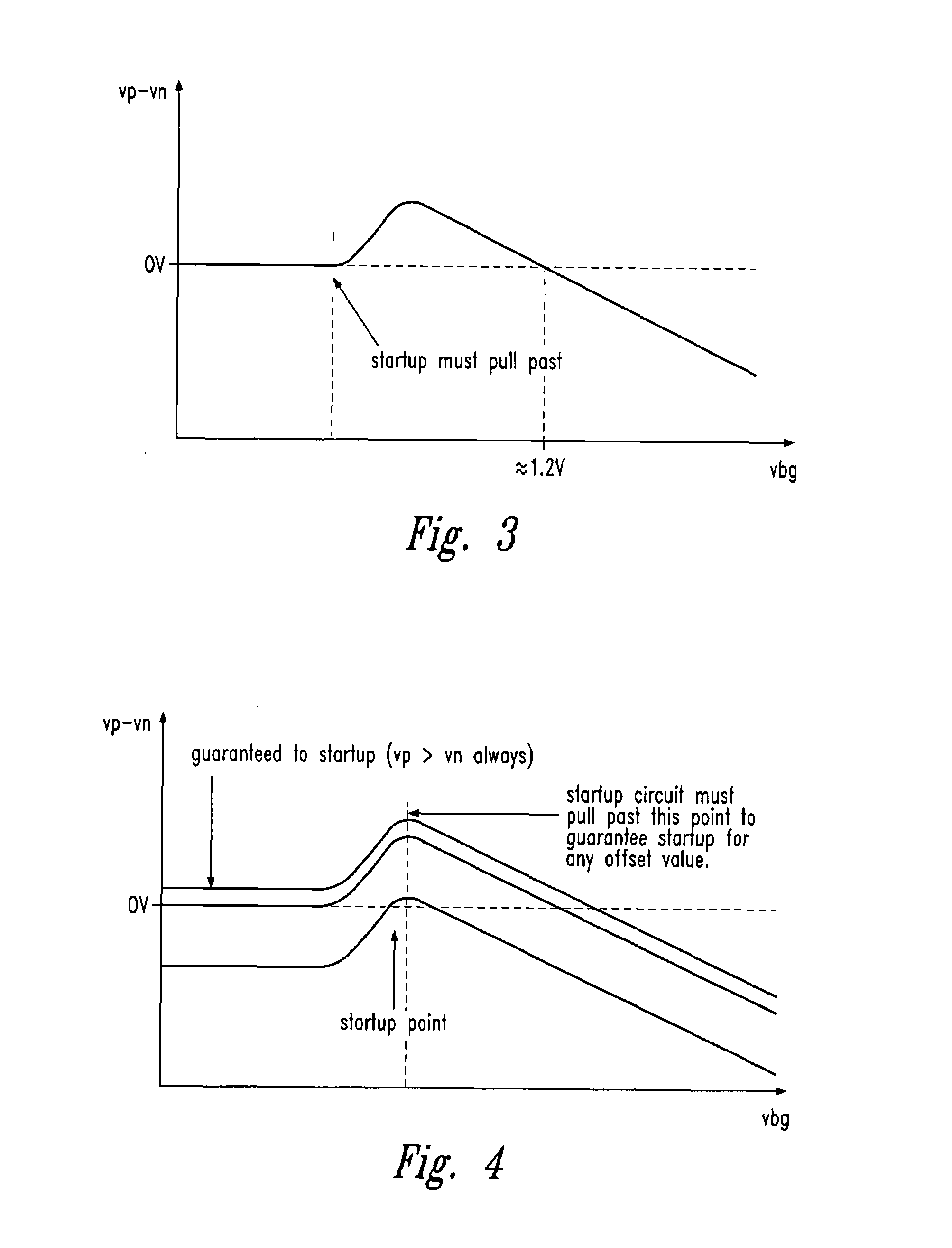
The band-gap reference circuit has multiple convergence points, meaning that the band-gap reference circuit might have multiple output voltages that it can become trapped at.
However, during power up of a bang-gap circuit, the output might also have a lower convergence point such as a 0.4V output voltage and become trapped at this value.
As recognized by the present inventor, disadvantages of conventional band-gap startup circuits include that their output current (used to startup the band-gap reference circuit) can vary with process, voltage and temperature (PVT).
As a result of these variations, conventional band-gap startup circuits do not always guarantee startup for a band-gap reference circuit.
Furthermore, as recognized by the present inventor, if the startup current does not turn off after the ban-gap circuit is at its desired operating point, the extra current from the startup circuit can cause the band-gap reference circuit to provide an incorrect output Vbg.

Method used


Image

  • Circuit and method for startup of a band-gap reference circuit
  • Circuit and method for startup of a band-gap reference circuit
  • Circuit and method for startup of a band-gap reference circuit

Examples


Embodiment Construction

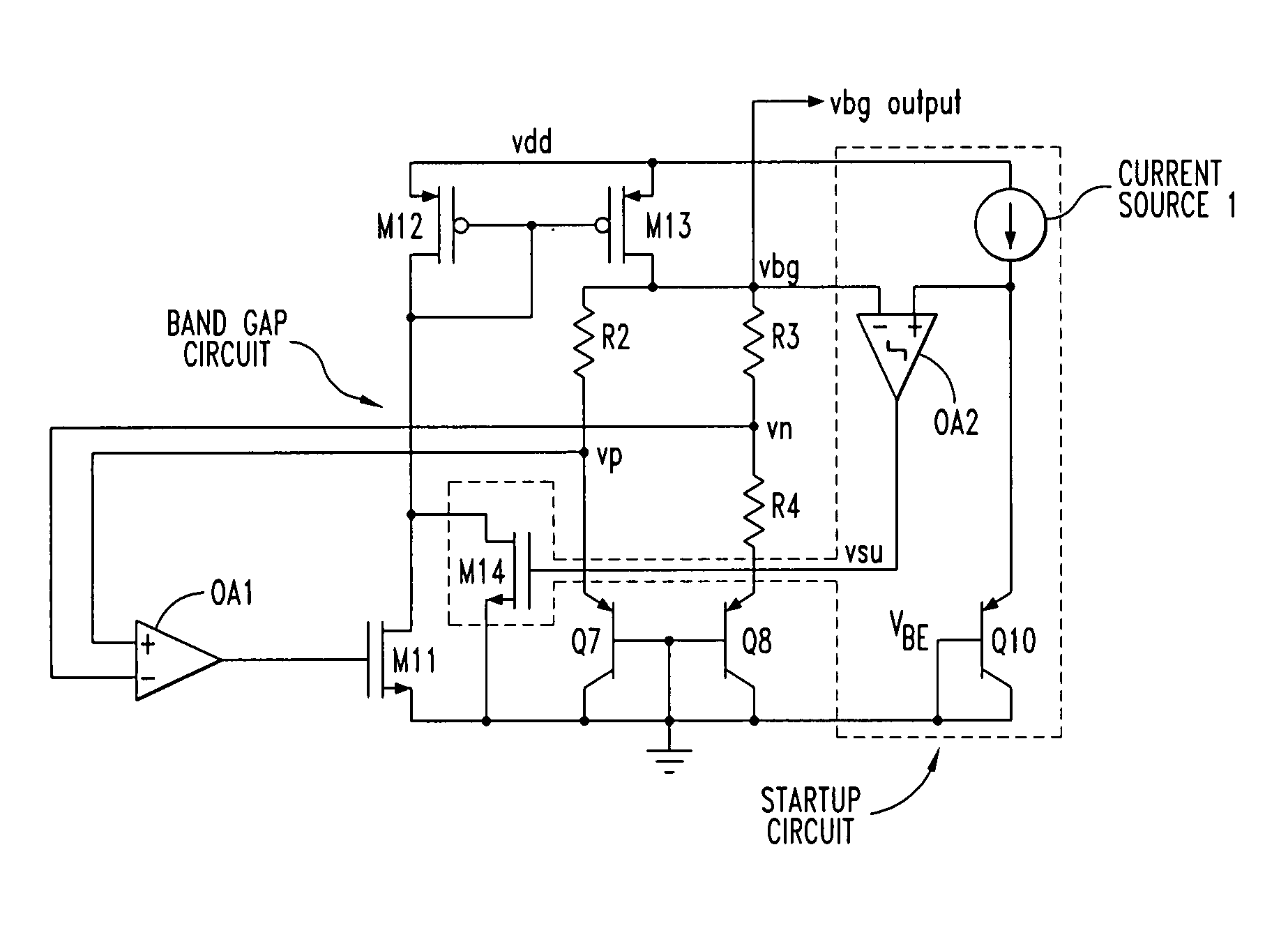
[0026]Embodiments of the present invention provide various circuits and methods for starting up a band-gap reference circuit. As will be described below, a startup reference signal is provided which may be derived, for example, from a diode voltage or a voltage across a transistor (such as a base-to-emitter voltage). The band-gap voltage output of the band-gap reference circuit is compared with the startup reference signal, and based on this comparison, a startup current is selectively activated and applied for starting up the band-gap reference circuit. Various embodiments of the present invention will now be described.

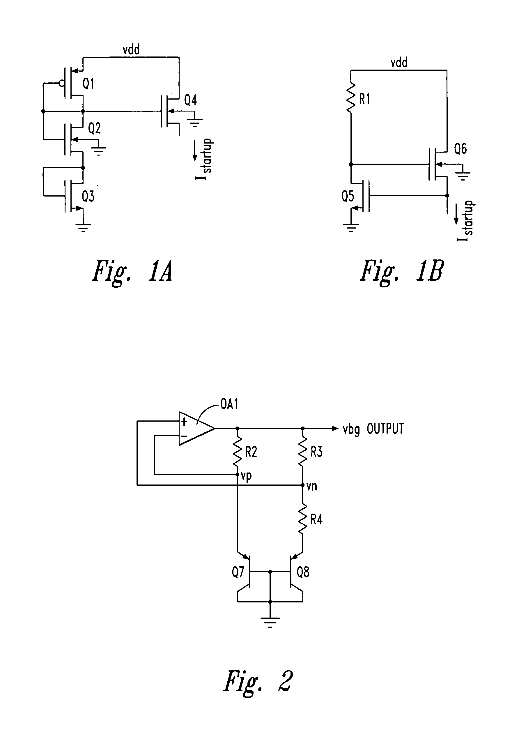
[0027]For clearer understanding of an improved startup circuit in accordance with one embodiment of the present invention, the mechanisms involved in startup of a band-gap reference are discussed. FIG. 2 shows a band-gap voltage reference circuit. The conventional band-gap voltage reference produces a stable reference on the Vbg node which is the output of the band-g...


PUM


Abstract

A circuit and method for starting up a band-gap reference circuit. In one example, a startup circuit compares a Vbg voltage output of a band-gap reference circuit to a voltage (such as Vbe) across a transistor in order to selectively control whether to inject current into the band-gap reference circuit during startup.

Description

CROSS REFERENCE TO RELATED APPLICATION[0001]This application claims priority under 35 U.S.C. 119(e) to U.S. Provisional Patent Application No. 60 / 527,203 entitled “A Failsafe Band-gap Reference Startup Circuit” filed Dec. 5, 2003, the disclosure of which is hereby incorporated by reference in its entirety.FIELD OF THE INVENTION[0002]This invention, in general, relates to electronic circuits and in particular to band-gap reference circuits and related startup circuits.BACKGROUND OF THE INVENTION[0003]A band-gap reference is a circuit that creates a voltage reference that is constant across process variation, supply voltage, and temperature. These circuits are used to generate output voltages of regulators, reference voltages for input / output circuits, precise biasing signals, and any other application requiring a constant voltage reference. Some band-gap references generate a current reference as well to be used in biasing circuits to provide desired operating points.[0004]Referring ...

Claims


Application Information

Patent Timeline
IPC IPC(8): G05F3/04G05F3/08G05F3/16
CPCG05F3/30
Inventor JACKSON, SCOTT A.
Owner GULA CONSULTING LLC
Learn More