Gas-discharge tube and display apparatus

a technology of gas-discharge tubes and display apparatuses, which is applied in the direction of discharge tubes luminescnet screens, gas-filled discharge tubes, multiple discharge path lamps, etc., can solve the problems of display defect, non-uniform surface tension applied to coated liquid, and the same situation as described above, so as to eliminate the dispersion of the position and stable discharge characteristics

Inactive Publication Date: 2007-10-16
SHINODA PLASMA
View PDF9 Cites 1 Cited by
  • Summary
  • Abstract
  • Description
  • Claims
  • Application Information

AI Technical Summary

Benefits of technology

[0015]The present invention has been achieved in order to solve the above described problems and an object thereof is to provide a gas-discharge tube with stable discharge characteristics by eliminating dispersion of the position of the electrode relative to the gas-discharge tube, and to provide a display apparatus in which a large number of such gas-discharge tubes are arranged.
[0016]In addition, another object of the present invention is to provide a gas-discharge tube with stable discharge voltage characteristics by increasing film thickness of a secondary electron emission film in the vicinity of the region where the discharge occurs so that the secondary electron emission efficiency increases, and to provide a display apparatus in which a large number of such gas-discharge tubes are arranged.
[0017]Furthermore, still another object of the present invention is to provide a gas-discharge tube with excellent brightening characteristics by forming a uniform film thickness of a secondary electron emission film and at the same time by increasing contact area between an electrode and a tubular body so as to expand the discharge region, and to provide a display apparatus in which a large number of such gas-discharge tubes are arranged.

Problems solved by technology

. . that can be easily maintained at equal intervals and, therefore, there is a fear that the same situation as described above may occur.
In the case where the voltage that must be applied to address electrode 97 in order to make this opposed discharge occur becomes higher than the voltage that can be applied to address electrode 97, it becomes impossible to make the opposed discharge occur resulting in a problem where a display defect occurs.
However, in the case where the above described gas-discharge tubes having a rectangular cross section as disclosed in Japanese Patent Application Laid-Open No. 61-103187 (1986) are utilized, the surface tension applied to the coated liquid becomes non-uniformed due to the inner peripheral shape of the cross section across the axis of the glass tubes being rectangular (including the case of being approximately elliptical) and therefore the coated liquid tends to collect to regions (bent portions) having a smaller curvature radius due to capillarity.
As a result of this, a problem arises wherein the secondary electron emission collects to the side surface in the configuration while the secondary electron emission efficiency deteriorates leading to a rise of the sustain voltage in the glass surface on the sustain electrode side due to the reduction in the film thickness of the secondary electron emission film 92.
However, in the case of the phosphor support member 94 where the cross section thereof is not point symmetrical, the tension at the time of the heat stretching does not become uniformed causing deformation easily.

Method used


Image

  • Gas-discharge tube and display apparatus
  • Gas-discharge tube and display apparatus
  • Gas-discharge tube and display apparatus

Examples


embodiment 1

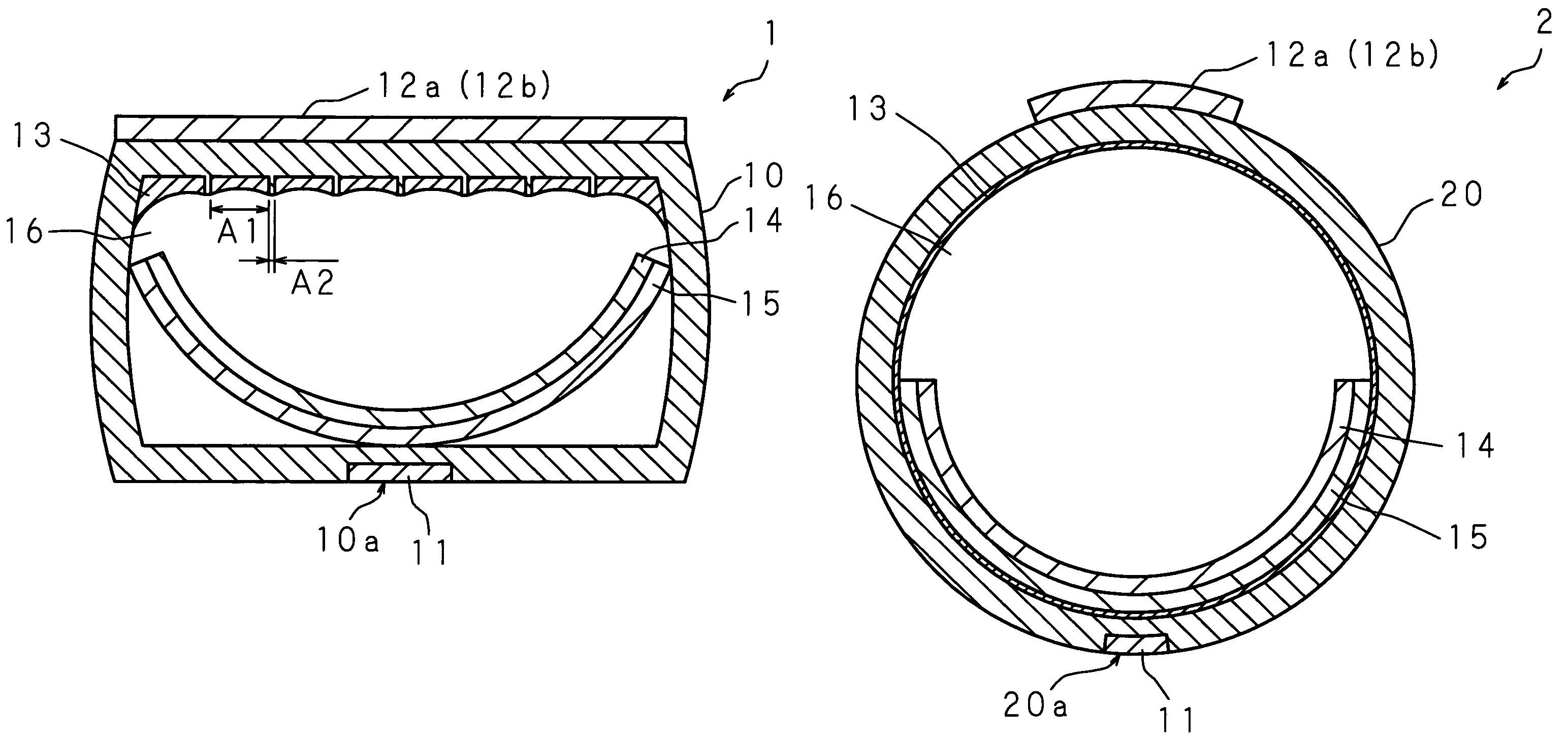
[0051]FIG. 3 is a schematic perspective view showing the outlook of a gas-discharge tube according to Embodiment 1 of the present invention and FIG. 4 is a schematic cross sectional view showing the structure along line II-II of FIG. 3. A gas-discharge tube 1 according to the present Embodiment 1 uses a glass tube 10 made from light transmissible glass (for example, borosilicate glass) as a tubular body whose inner periphery and outer periphery of the cross section across the axis are both approximately rectangular. A trench 10a is provided in an axial direction of the glass tube 10 on the outside of one side (the side-facing the discharge surface) within glass tube 10, and an address electrode 11 is placed in this trench 10a. On the other hand, a plurality of sustain electrodes 12a and 12b is placed at predetermined intervals parallel to the direction crossing the axial direction of the glass tube 10 on the external surface of the side that faces the side of glass tube 10 where the...

embodiment 2

[0065]FIG. 9 is a schematic cross sectional view showing the structure of a gas-discharge tube according to Embodiment 2 of the present invention. A gas-discharge tube 3 according to Embodiment 2 is made from a glass tube 30 as a main body where the inner periphery and the outer periphery of the cross section across the axis are both rectangular shape. A trench 30a is provided in the axial direction of the glass tube 30 on one surface (the surface facing the discharge surface) among the external surfaces of the glass tube 30. The thickness of the glass tube 30 is approximately constant, and the inside of the glass tube 30 of a portion where the trench 30a is provided on the external surface has a shape protruding toward the inside. An address electrode 11 is placed in the trench 30a. Sustain electrodes 12a and 12b are placed at a predetermined interval parallel to the direction crossing the axial direction of the glass tube 30 on the external surface of the glass tube 30 of the side...

embodiment 3

[0068]FIG. 10 is a schematic cross sectional view showing the structure of a gas-discharge tube according to Embodiment 3. The gas-discharge tube 4 according to Embodiment 3 is made from a glass tube 40 as a main material whose inner periphery of the cross section across the axis is circular shape, and the outer periphery of the cross section across the axis is approximately rectangular shape. An address electrode 11 is placed in the axial direction of the glass tube 40 on an external surface of the glass tube 40. Sustain electrodes 12a and 12b are placed at a predetermined distance parallel to the direction crossing the axial direction on the external surface of the glass tube 40, opposed to the address electrode 11. The address electrode 11 and the sustain electrodes 12a and 12b are placed so as to cross each other in the plan view, and each region defined by the intersection between the address electrode 11 and the sustain electrodes 12a and 12b becomes a unit emitting region (ce...


PUM


Abstract

A gas-discharge tube has a glass tube as its main body and a trench is provided in the axial direction of the glass tube on one surface (the surface opposed to the discharge surface) among the external surfaces of the glass tube. An address electrode is placed in the trench. The inner surface of the region of the glass tube where sustain electrodes are placed is formed to have a microscopic unevenness. A secondary electron emission film is formed on this inner surface where the unevenness is formed. In addition, a phosphor support member, whose cross section across the axis is in approximately a C-shape and where a phosphor layer has been formed in advance on the inner surface, is placed inside of the glass tube. Stable discharge characteristics is obtained by eliminating dispersion of the position of an electrode, relative to the gas-discharge tube.

Description

BACKGROUND OF THE INVENTION[0001]1. Field of the Invention[0002]The present invention relates to a gas-discharge tube in which a discharge gas is sealed as a discharge medium and to a display apparatus that can display images, (video image), including a dynamic image, by aligning a large number of such gas-discharge tubes in parallel form.[0003]2. Description of Related Art[0004]Large scale display apparatuses have been proposed wherein a gas-discharge tube is constructed such that a phosphor is provided inside of a long and narrow transparent insulating tube and a discharge gas is sealed in the tube in the same manner as PDP (Plasma Display Panel) using the same illumination principle and wherein a large number of such gas-discharge tubes are aligned in parallel form and thereby video images, including a dynamic image, can be displayed (see, for example, Japanese Patent Application Laid-Open No. 61-103187 (1986)). Such a display apparatus is a self-emission type display apparatus t...

Claims


Application Information

Patent Timeline
Patent Type & Authority Patents(United States)
IPC IPC(8): H01J1/62H01J65/00H01J11/18H01J11/24H01J11/40H01J61/92
CPCH01J11/18H01J11/20H01J11/22
Inventor TOKAI, AKIRAYAMADA, HITOSHIISHIMOTO, MANABUAWAMOTO, KENJIYAMAZAKI, YOSUKEHIRAKAWA, HITOSHINAKAZAWA, AKIRASHINOHE, KOJI
Owner SHINODA PLASMA
Why Eureka
Try Eureka