Light adjustable multifocal lenses
a multi-angle, adjustable technology, applied in the field of optical elements, can solve problems such as swelling of the element in the area
- Summary
- Abstract
- Description
- Claims
- Application Information
AI Technical Summary
Benefits of technology
Problems solved by technology
Method used
Image
Examples
example 1
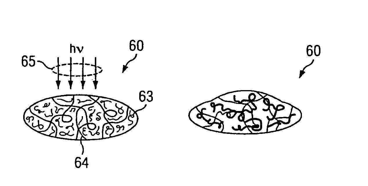
[0085]Materials comprising various amounts of (a) poly-dimethylsiloxane endcapped with diacetoxymethylsilane (“PDMS”) (36000 g / mol), (b) dimethylsiloxane-diphenylsiloxane copolymer endcapped with vinyl-dimethyl silane (“DMDPS ”) (15,500 g / mol), and (c) a UV-photoinitiator, 2,2-dimethoxy-2-phenylacetophenone (“DMPA”) as shown by Table 1 were made and tested. PDMS is the monomer which forms first polymer matrix, and DMDPS and DMPA together comprise the refraction modulating composition.
[0086]
TABLE 1PDMS (wt. %)DMDPS (wt. %)DMPA (wt. %).sup.a190101.5280201.5375251.5470301.5.sup.a wt % with respect to DMDPS.
[0087]Briefly, appropriate amounts of PMDS (Gelest DMS-D33; 36000 g / mol), DMDPS (Gelest PDV-0325; 3.0-3.5 mole % diphenyl, 15,500 g / mol), and DMPA (Acros; 1.5 wt % with respect to DMDPS) were weighed together in an aluminum pan, manually mixed at room temperature until the DMPA dissolved, and degassed under pressure (5 mtorr) for 2-4 minutes to remove air bubbles. Photosensitive pris...
example 2
Synthesis RMC Monomers
[0089]As illustrated by Scheme 1, commercially available cyclic dimethylsiloxane tetramer (“D4”), cyclic methylphenylsiloxane trimer (“D3′”) in various ratios were ring-opened by triflic acid and bis-methacryloxylpropyltetramethyldisiloxane (“MPS”) were reacted in a one pot synthesis. U.S. Pat. No. 4,260,725; Kunzler, J. F., Trends in Polymer Science, 4: 52-59 (1996); Kunzler et al. J. Appl. Poly. Sci., 55: 611-619 (1995); and Lai et al., J. Poly. Sci. A. Poly. Chem., 33: 1773-1782 (1995).
[0090]
[0091]Briefly, appropriate amounts of MPS, D4, and D3′ were stirred in a vial for 1.5-2 hours. An appropriate amount of triflic acid was added and the resulting mixture was stirred for another 20 hours at room temperature. The reaction mixture was diluted with hexane, neutralized (the acid) by the addition of sodium bicarbonate, and dried by the addition of anhydrous sodium sulfate. After filtration and rotovaporation of hexane, the RMC monomer was purified by further f...
example 3
Fabrication of Intraocular Lenses (“IOL”)
[0099]An intraocular mold was designed according to well-accepted standards. See e.g., U.S. Pat. Nos. 5,762,836; 5,141,678; and 5,213,825. Briefly, the mold is built around two plano-concave surfaces possessing radii of curvatures of −6.46 mm and / or −12.92 mm, respectively. The resulting lenses are 6.35 mm in diameter and possess a thickness ranging from 0.64 mm, 0.98 mm, or 1.32 mm depending upon the combination of concave lens surfaces used. Using two different radii of curvatures in their three possible combinations and assuming a nominal refractive index of 1.404 for the IOL composition, lenses with pre-irradiation powers of 10.51 D (62.09 D in air), 15.75 D (92.44 in air), and 20.95 D (121.46 D in air) were fabricated.
PUM
| Property | Measurement | Unit |
|---|---|---|
| diameter | aaaaa | aaaaa |
| displacement distance | aaaaa | aaaaa |
| angle | aaaaa | aaaaa |
Abstract
Description
Claims
Application Information
 - R&D
- Intellectual Property
- Life Sciences
- Materials
- Tech Scout
- Unparalleled Data Quality
- Higher Quality Content
- 60% Fewer Hallucinations
Browse by: Latest US Patents, China's latest patents, Technical Efficacy Thesaurus, Application Domain, Technology Topic, Popular Technical Reports.
© 2025 PatSnap. All rights reserved.Legal|Privacy policy|Modern Slavery Act Transparency Statement|Sitemap|About US| Contact US: help@patsnap.com


