
Method of operating fuel cell

a fuel cell and fuel cell technology, applied in the field of fuel cell operation, can solve the problems of deterioration of fuel cell performance, increased equipment size, and higher manufacturing cost, and achieve the effects of simple and inexpensive, restoring normal performance, and increasing the power rating of system components

Inactive Publication Date: 2007-10-02
MITSUBISHI ELECTRIC CORP
View PDF3 Cites 5 Cited by
  • Summary
  • Abstract
  • Description
  • Claims
  • Application Information

AI Technical Summary

Benefits of technology

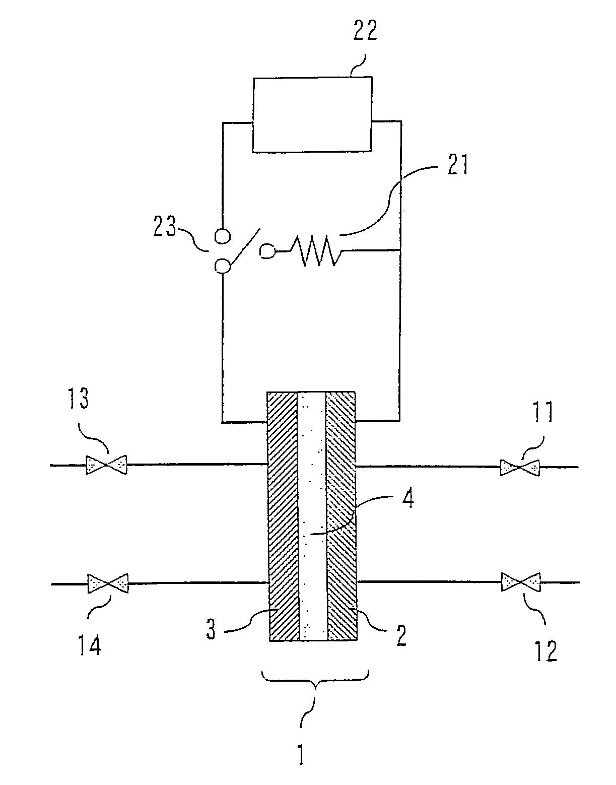
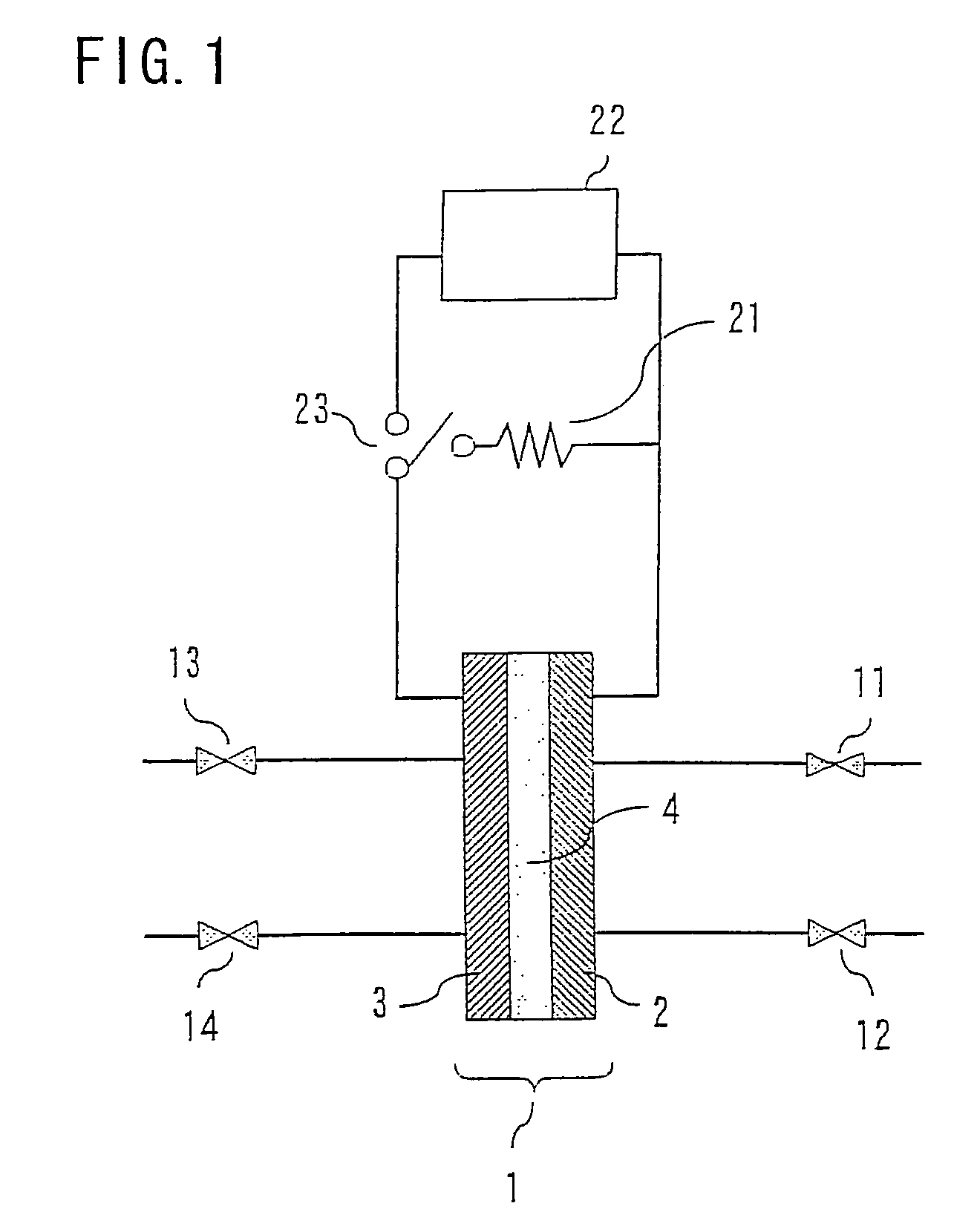
[0013]Intended to provide a solution to the aforementioned problems of the prior art, the invention has as an object the provision of a simple and inexpensive method of starting up a fuel cell power generating system by removing oxides deposited on an oxidant electrode of a fuel cell to restore normal performance thereof without the need for increasing power ratings of system components.
[0015]This method of operating the fuel cell of the invention makes it possible to recondition the oxidant electrode by reducing the oxides deposited on the oxidant electrode and restore normal performance of the fuel cell in a simple and inexpensive way, thereby permitting restart of a fuel cell power generating system without the need for increasing power ratings of system components.

Problems solved by technology

This phenomenon is considered to occur as oxides deposit on a surface of platinum (Pt) used in the oxidant electrode and an effective area of the active Pt surface decreases as a result of an increase in oxide-covered areas, thereby causing deterioration of fuel cell performance.
To meet this requirement, wirings, an AC-DC converter, a circuit breaker and other components of a fuel cell system must have higher power ratings than would be necessary under normal operating conditions, resulting in an increase in an increased equipment size and a higher manufacturing cost.

Method used


Image

  • Method of operating fuel cell
  • Method of operating fuel cell

Examples


examples

[0036]Table 1 shows the results of experiments conducted to evaluate the fuel cell performance in terms of voltage drop ratio per operating cycle observed when the fuel cell power generating system of the invention was repeatedly run and stopped 100 times with varying durations of startup phase operation (during which the potential difference between the two electrodes 2, 3 was maintained at 0.1 V or less with the two electrodes 2, 3 interconnected). Referring to Table 1, the duration of the startup phase operation was 1 minute or more in Example 1, 10 seconds or more in Example 2, 1 second or more in Example 3, less than 1 second (approximately 0.5 second) in Comparative Example 1, and 0 seconds in Comparative Example 2. The experimental results indicate that the voltage drop ratio was the lowest in Example 1 and relatively low in Examples 2 and 3, whereas Comparative Example 2 (in which the startup phase operation was not performed) exhibited a maximum voltage drop ratio. While th...


PUM

PropertyMeasurementUnit
electrode potentialaaaaaaaaaa
oxidation reduction potentialaaaaaaaaaa

Abstract

A method of operating a fuel cell including a fuel electrode, an oxidant electrode, and an electrolyte layer having hydrogen ion conductivity sandwiched between the fuel electrode and the oxidant electrode, so that the fuel cell generates electricity as a result of an electrochemical reaction between a fuel and an oxidant. Each time the fuel cell is started from a non-operating condition, the fuel is supplied to the fuel electrode with the fuel electrode and the oxidant electrode electrically interconnected to produce hydrogen at the oxidant electrode by provoking electrochemical reactions expressed by the chemical equations H2→2H++2e− and 2H++2e−→H2 at the fuel electrode and the oxidant electrode, respectively, reducing oxides on the oxidant electrode, using the hydrogen produced at the oxidant electrode. Then, the oxidant is supplied to the oxidant electrode to begin normal continuing operation of the fuel cell.

Description

BACKGROUND OF THE INVENTION[0001]1. Field of the Invention[0002]The present invention relates to a method of operating a fuel cell used in an electric vehicle or a stationary power generating system, for example.[0003]2. Description of the Background Art[0004]A fuel cell is a device produced by sandwiching a layer of an electrolyte between two electrodes (oxidant and fuel electrodes). The fuel cell converts chemical energy directly into electric energy by supplying a fuel to one of the electrodes and an oxidant to the other, thereby producing an electrochemical reaction between the fuel and the oxidant. There are several types of fuel cells. Today, solid polymer electrolyte fuel cells using a solid polymer electrolyte membrane having proton conductivity as the electrolyte layer are watched with keen interest as fuel cells suited for producing high output power.[0005]Main constituent elements of a solid polymer fuel cell are an anode and a cathode which together constitute two facing...

Claims


Application Information

Patent Timeline
Patent Type & Authority Patents(United States)
IPC IPC(8): H01M8/04
CPCH01M8/04223Y02E60/50H01M2008/1095H01M8/04231H01M8/04228H01M8/241H01M8/04225H01M8/2457H01M8/04302
Inventor FUKUMOTO, HISATOSHIKURIKI, HIRONORINISHIMURA, TAKASHIMATSUMOTO, SHUICHI
Owner MITSUBISHI ELECTRIC CORP
Learn More