Eureka AIR delivers breakthrough ideas for toughest innovation challenges, trusted by R&D personnel around the world.

Real-time control system development tool with input pins providing values used by component during execution

a real-time control system and input pin technology, applied in the direction of electrical programme control, instrumentation, program control, etc., can solve the problems of inability to meet the demands of such complex systems, the development tools of prior art for such complex systems are notoriously complex, and the difficulty of building software for real-time control systems is hug

Inactive Publication Date: 2007-09-25
REAL TIME INNOVATIONS
View PDF38 Cites 54 Cited by
  • Summary
  • Abstract
  • Description
  • Claims
  • Application Information

AI Technical Summary

Benefits of technology

[0027]In addition to combining event-driven and sampled-data processing, COGs are also able to bridge procedural and object-oriented design. Both event-driven and continuous data applications are most naturally thought of as occurring procedurally. Control engineers are used to thinking in this manner; control systems are built from blocks that process inputs and produce outputs. On the other hand, larger subsystems are most often best modeled as objects. Objects are usually thought of as executing independently of and concurrently with other objects. They communicate by exchanging asynchronous messages. Object-oriented design is fundamentally different than procedural thinking. As a COG is an object that is built from procedural components, it neatly bridges the gap between procedural thinking (more efficient at low engineering levels) and powerful object-oriented thinking (more efficient at higher system design levels).
[0029]By contrast, the present invention uses COGs to model complex real-time systems, and in particular is well-suited for modeling electromechanical systems. This utilization of a specific object model bestows many benefits. For instance, it shortcuts much of the tedious analysis and object hierarchy design phase. The present invention provides specific data structures and reusable objects that fit specific problem domains. It allows problems to be modeled faster and complex code to be working more quickly. In addition, the present invention is not limited to providing only a top-down design approach as in UML.
[0031]This top-down / bottom-up combined approach is very intuitive. It allows designers to work simultaneously at different levels of abstraction-today on the overall design, tomorrow on a specific subsystem. This makes it easy to iterate between partially-specified designs and fully-specified subsystems. In one aspect of the invention, interfaces are defined between subsystems during top-down decomposition. As long as the interfaces are unique, top-down decomposition continues. When the design is refined to the point that existing components can be used, these components are then used to fill in the functionality needed. Thus, design may begin from the top-down, but eventually commonly defined components are reached during the process. Prior art tools have provided no mechanism for this combined design to occur.
[0034]Under mode mapping, the user is allowed to choose in a simple and intuitive manner which components of the control system will run in which mode. Each component may have a number of modes, each identified by a name. For a group of components (e.g. a control system for a robot arm), a mode may be defined for this whole group by picking and choosing desirable modes for the components contained within. Thus, for a given mode for the whole system, only selected components are “active” and will run. This allows a user to choose at high level which code will be allowed to run for a given situation.
[0036]Within a given processor, each component of a control system may be assigned to individual execution threads within that processor simply by naming a thread. Each thread may be configured to execute at a different rate, thus providing different rates of executions for different components within one control system. Also a composite component such as a composite object group or a finite state machine may be assigned to multiple threads to accommodate the different needs of its constituent components. Each component in the hierarchy of a system diagram is assigned a logical rate that is eventually mapped to an actual rate of a thread. In this way, a component with its hierarchy of logical rates is reusable and may be inserted into a different real-time system that might have different threads and rates available. When used in this way, the logical rates of a component are simply mapped to whatever actual rates that are available (which may number greater or fewer than the logical rates); each lower-level component is thus assigned to an actual rate.

Problems solved by technology

Real-time system software is notoriously complex.
Building software for real-time control systems is a huge challenge.
Prior art development tools for such complex systems have simply not been able to keep pace with the demands of these complex systems.
Development tools built for other real-time applications—such as telecommunications or databases—are not well suited to the challenges of complex control systems.
In particular, they are not well-suited for complex electromechanical systems.
But often they do not truly accelerate development.
In particular, prior art object-oriented modeling tools are useful for some systems as will be described below, but are not well suited for the needs of complex, real-time control systems.
However, in most systems they only apply to a small percentage of the total problem.
They are not good programming systems, and thus cannot handle truly complex systems that require significant custom coding.
In particular, mathematical simulation tools are useful for certain applications as will be described below, but are also not especially well-suited for the needs of complex, real-time control systems.
However, the top-down design process has a serious flaw: it leads to unique solutions to every problem.
None of the resulting subsystems can be reused easily.
However, like a concept car, the result will contain many strange parts that all have to be painstakingly handcrafted.
In particular, various prior art object modeling tools work well for general problem areas, but are not optimal for complex, real-time control systems.
They are not well-suited for, and are unable to handle, sampled-data processing mainly because the problems they address do not require it.
In general, these prior art object modeling tools do not provide sampled-data processing that is often critical in complex real-time systems.
Specifically, these tools have no concept of matrices and are unable to implement detailed mathematical calculations nor evolve over time.
These deficiencies mean that these tools may not be well-suited for certain real-time systems that require such complex mathematical simulations.
However, without the overall picture and goal in mind, it often does not result in a clean division of functionality.
The bottom-up design process provides no overall view to communicate the goals and progress of a project between team members.
Only true reuse generates the leverage that results in large dividends.
Small, functional components are easy to reuse, but do not provide large benefits.
But complex components have complex interfaces and specific functions.
The more complex the component, the harder it is to reuse.
As such, they provide advantages for certain narrow problem areas, but are not well-suited for modeling complex real-time systems.
These simulation tools, however, are not object-oriented programming tools and are not well-suited for modeling systems or for building complex real-time systems.
Specifically, these tools are useful for building a data flow model of the world where intense number crunching is necessary, but they do not provide objects, methods upon objects, or the other beneficial features of object-oriented programming tools.
Unfortunately, often complex problems require both a top-down and a bottom-up approach.
Of course, real-life control systems are incredibly more complex.
This technique is confusing and hard to understand and maintain.
These lines can become very complex and difficult to manage, let alone simply trying to figure out which mode the system is in.
Furthermore, many complex systems often radically change modes of operation during execution.
The designs of these systems may fail to consider the wide-ranging effects of these mode changes and “run out of steam” due to the complexity of the branches and switch blocks required.
It can be time-consuming and complex to redo the system to make a simulation.
The fast rate required for a particular sensor may be incompatible with the slower sampling rate of a different element.
Simply slowing the whole system down to accommodate one slow rate element is not efficient.
Conversely, speeding up the whole system to run at a fast rate is not feasible if one particular sensor or data sampling element cannot cycle that quickly.
Further, it can be unwieldy to break the system into different pieces for different processors, only to try to cobble the system back together to make it function correctly.

Method used


Image

  • Real-time control system development tool with input pins providing values used by component during execution
  • Real-time control system development tool with input pins providing values used by component during execution
  • Real-time control system development tool with input pins providing values used by component during execution

Examples


Embodiment Construction

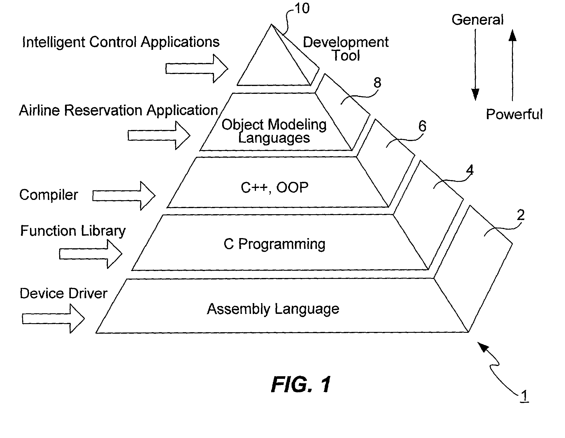
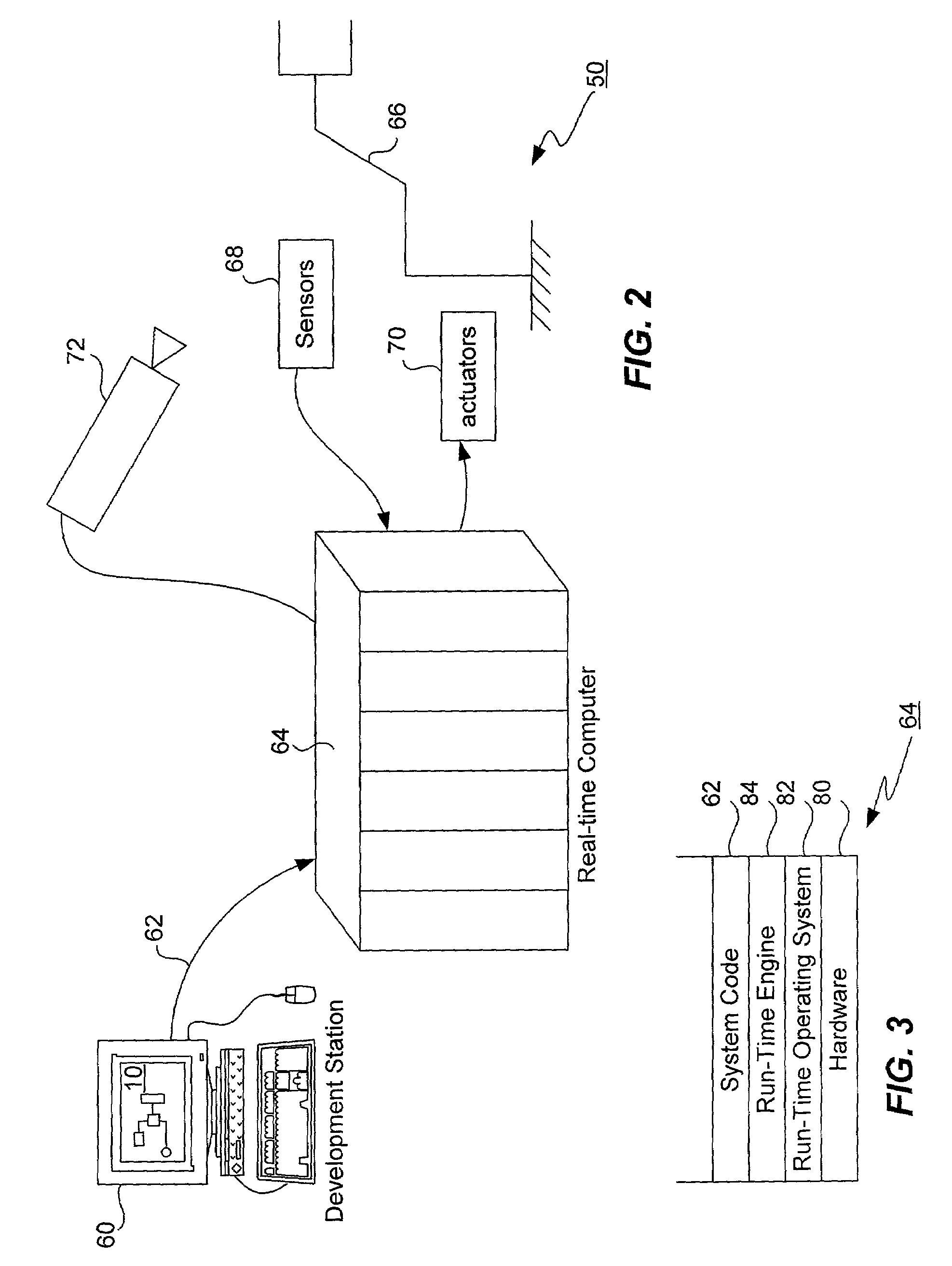
[0072]Real-time software for control systems is complex. There are excellent control and simulation tools, but often they do not address the complex programming needs of many systems. There are general programming tools, but often they do not provide useful facilities for real-time control problems. What is missing is a programming tool with prebuilt architectures designed specifically for real-time control problems. Although the present invention is suitable for use with a wide range of intelligent control applications, real-time electromechanical systems in particular will often be highlighted in the course of this disclosure to provide a working example.

[0073]Control systems may be complex because of the mathematical algorithms they contain, or because they contain many concurrent elements. For example, electromechanical systems exhibit both of these types of complexity to some extent, but more importantly are faced with computational structure complexity. Electromechanical syste...


PUM


Abstract

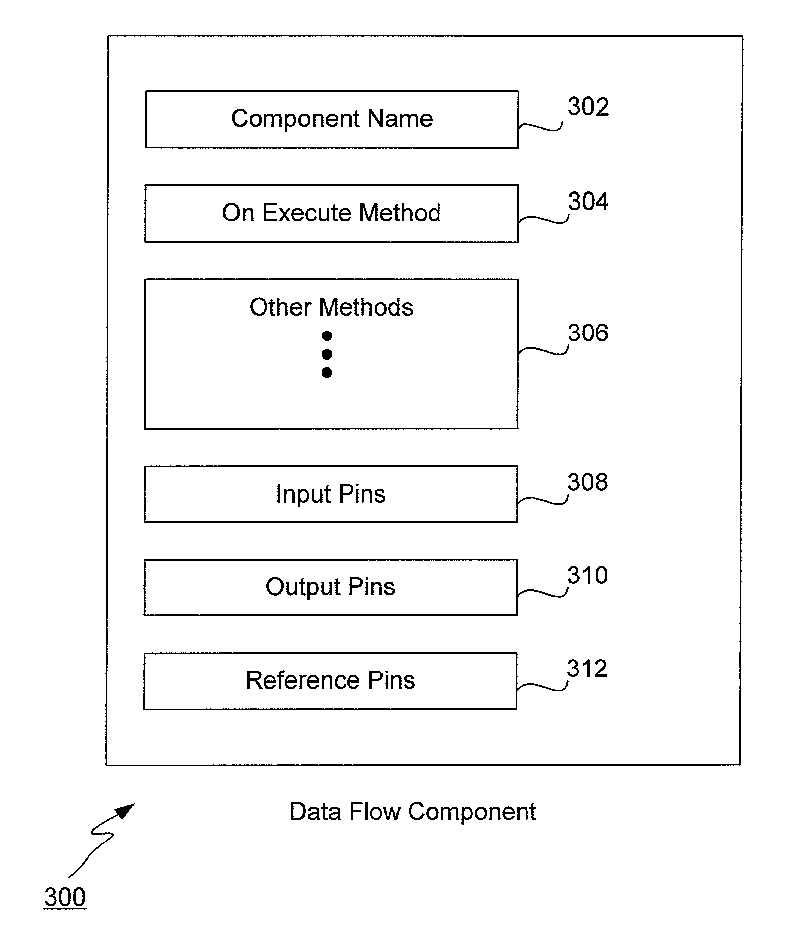
A development tool combines advantages of a simulation tool with an object-oriented modeling tool, including a real-time mathematical matrix library and an object model. The tool is applicable to any intelligent control system. A composite object group (COG) contains both sampled-data and event-driven capabilities. COGs merge procedural and object-oriented programming, and provide explicit, graphical integration of both types of processing and are fully hierarchical. A control system is built up of object-oriented components, including these types: atomic, interface, data flow and state transition. A finite state machine (FSM) component is built from states, transitions, events and state transition components. Data flow components provide sampled-data capabilities. FSMs provide event-drive capabilities. Each component may include methods and attributes. A COG includes any type of component including COGs, graphical interconnections between components, and is used to graphically build a model of a control system.

Description

[0001]This application is a divisional of U.S. patent application Ser. No. 09 / 259,179, filed Feb. 26, 1999 now U.S. Pat. No. 6,718,533 entitled “Real-time Control System Development Tool,” which is hereby incorporated by reference.[0002]This application is related to U.S. patent application Ser. No. 10 / 207,603, filed on the same date herewith, having the same title, which is hereby incorporated by reference.[0003]This invention was partially funded under National Institute of Standards and Technology (NIST) Advanced Technology Program (ATP) contract No. 70NANB5H1163. The government has certain rights in this invention.FIELD OF THE INVENTION[0004]The present invention relates generally to a programming tool for software development. More specifically, the present invention relates to a tool for developing and executing real-time control systems.BACKGROUND OF THE INVENTION[0005]Real-time system software is notoriously complex. Large projects must balance the special needs of real-time...

Claims


Application Information

Patent Timeline
Patent Type & Authority Patents(United States)
IPC IPC(8): G06F9/44G05B19/42
CPCG06F8/10
Inventor SCHNEIDER, STANLEY A.CHEN, VINCENT W.PARDO-CASTELLOTE, GERARDOWANG, HOWARD H.JOSHI, RAJIVE
Owner REAL TIME INNOVATIONS
Why Eureka
Eureka Blog
Learn More