
Magneto-optical recording using a heating element

a heating element and magnetic recording technology, applied in the field of magnetic recording methods, can solve problems such as the difficulty of mounting magnetic field generation means, and achieve the effects of easy integration of magnetic heads, small and thin magnetic disk recording apparatuses

Inactive Publication Date: 2007-09-25
HITACHI LTD
View PDF13 Cites 4 Cited by
  • Summary
  • Abstract
  • Description
  • Claims
  • Application Information

AI Technical Summary

Benefits of technology

[0041]An object of the present invention is to provide a magnetic recording method and a magnetic recording medium which can achieve both robustness for thermal decay of magnetization and noise reduction and can realize an ultra-high recording density of 1 Tb / in2 and a magnetic disk recording apparatus permitting integration.
[0043]According to the magnetic recording method, magnetic recording medium and magnetic disk recording apparatus of the present invention, magnetization of the printed layer is small in magnetic field recording and is large in printing by heating. The recording performance of overwrite remains high to increase the long-period stability to reduce noise in reproduction. A high areal recording density exceeding 300 gigabits per square inch can be realized.
[0053]Through a series of the recording operations, the crystal particles in the first and second recording layers adjacent via the intermediate layer behave as a substantially one cluster. Consequently, the substantial crystal particle volume of the crystal particles in the first and second recording layers is increased. The magnetic domain structure is stable to reduce medium noise for realizing a magnetic recording medium whose robustness for thermal decay of magnetization is improved.
[0055]The magnetic recording method for recording a magnetization pattern onto a magnetic recording medium applying the present invention performs, with different timings, magnetic field application for recording a magnetization pattern onto the first recording layer and heating for printing the magnetization pattern of the first recording layer onto the second recording layer. The integration of a magnetic head is easy and the magnetic disk recording apparatus can be smaller and thinner.

Problems solved by technology

The most major problem of applying the method (1) to a magnetic disk recording apparatus is in integration of a magnetic head.
It is very difficult to mount magnetic field generation means and magnetic recording medium heating means on one slider constructing a magnetic head.
Realizing a magnetic disk recording apparatus using the method (1) as a recording method performing magnetic field application and medium heating at the same time is very disadvantageous as a technique used in a magnetic disk recording apparatus which is strongly required to be smaller and thinner.
When applying the method to the magnetic disk recording apparatus, some problems arise.
This is disadvantageous as the technique of the magnetic disk recording apparatus which is required to be smaller and thinner.

Method used


Image

  • Magneto-optical recording using a heating element
  • Magneto-optical recording using a heating element
  • Magneto-optical recording using a heating element

Examples


example 1

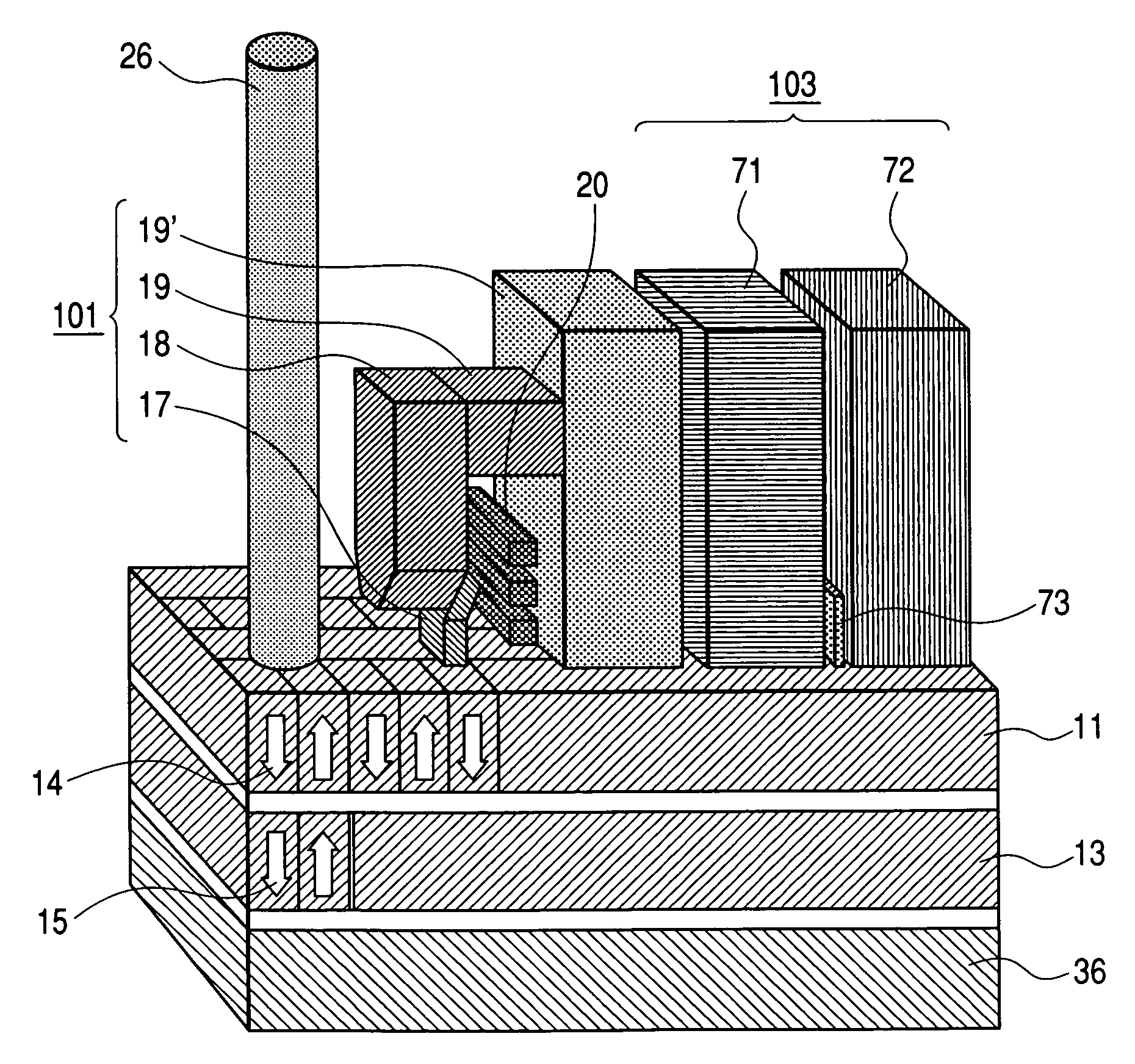
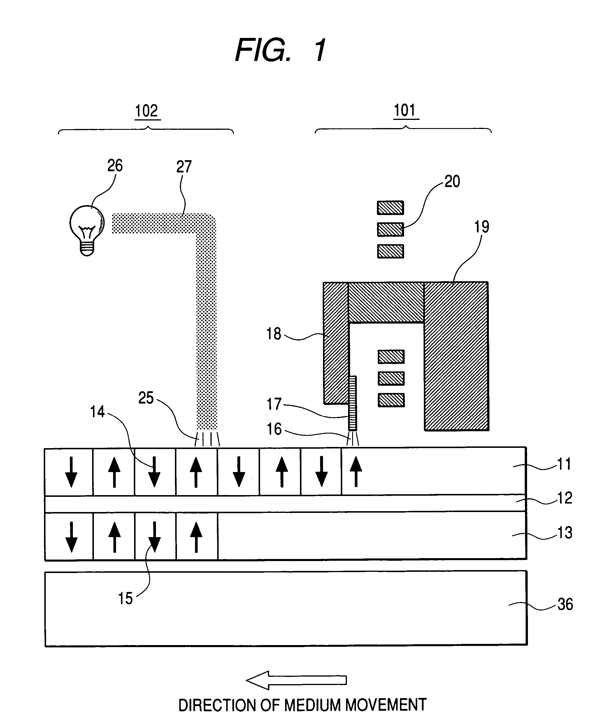
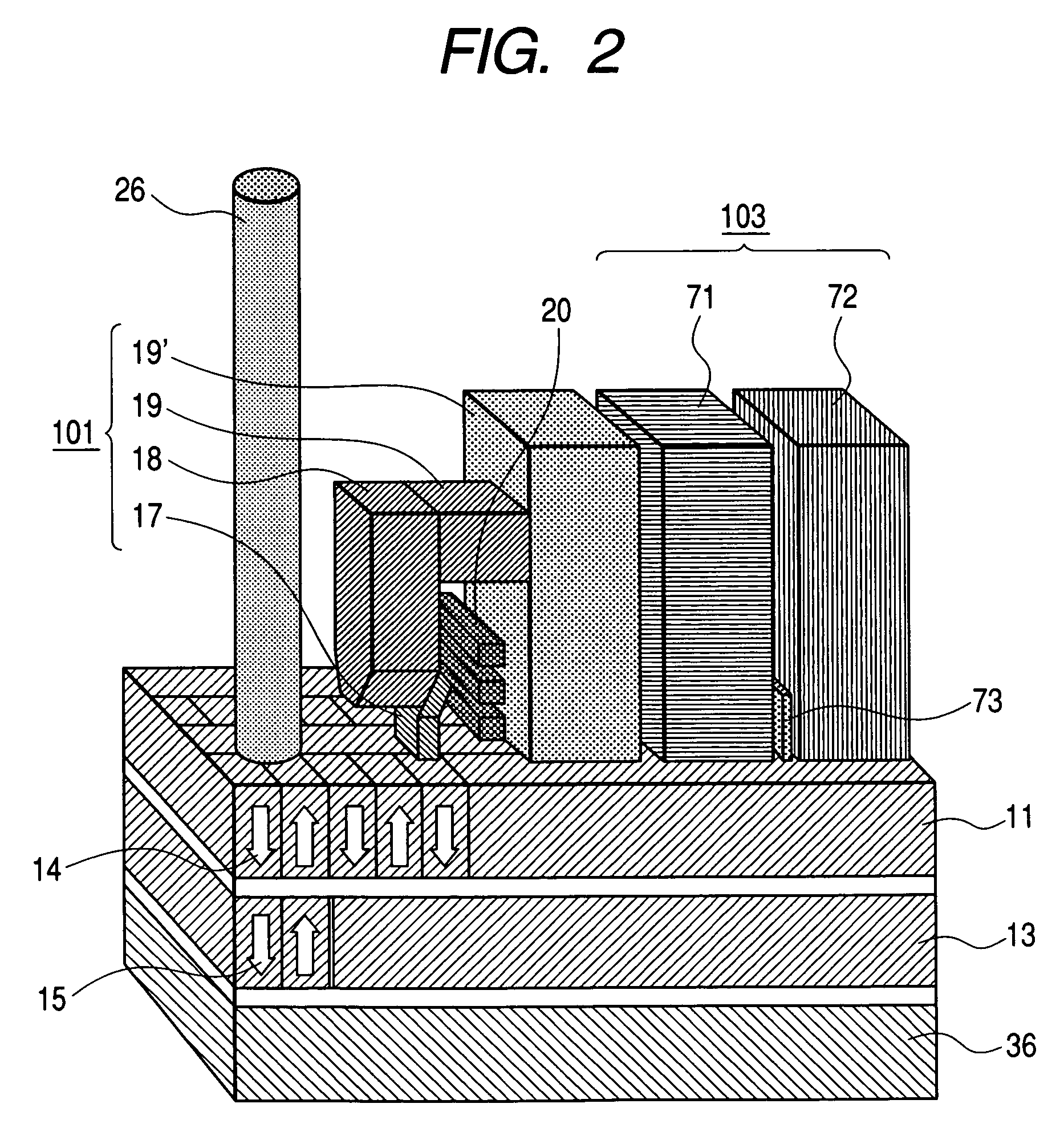
[0072]FIG. 1 is a schematic diagram of a magnetic recording system embodying the present invention. A reproducing device is omitted. FIG. 2 shows a perspective view of the same system to which the reproducing device is added.

[0073]A magnetic recording device 101 has a magnetic pole 17 generating a recording field 16, a yoke 18 for supplying a magnetic flux thereto, a return path 19, and a conductor coil 20 for magnetizing these. Heating means 102 has a laser light source 26 and a waveguide 27. A semiconductor laser generating a light having a wavelength below 500 nm is desirably used as the laser light source 27.

[0074]The magnetic recording device 101 and a flux keeper layer 36 form a magnetic path in which a magnetic flux is refluxed. A magnetic recording medium is interposed therein. The recording field 16 from the magnetic pole 17 toward the flux keeper layer 36, that is, a magnetic field substantially perpendicular to the surface of the magnetic recording medium is applied.

[0075...

example 2

[0097]FIG. 7 is a perspective view showing the state during an overwrite operation which is an operation writing new recorded data onto old recorded data in the magnetic recording system for thermo-magnetic printing applying the present invention.

[0098]After forming a pattern on the first recording layer by a magnetic field from the magnetic pole 17, noting the state before heating-up it by the heating means, the magnetization pattern of the first recording layer 11 is different from the magnetization pattern of the second recording layer 13. Depending on a location in which the recording pattern is formed, a magnetostatic field from the magnetization pattern of the second recording layer 13 may deteriorate the magnetization of the first recording layer 11.

[0099]This means that the pattern of old recorded data interferes with new recorded data, which deteriorates the overwrite characteristic as the recording characteristic. To prevent the interference, it is essential to form the in...

example 3

[0104]FIG. 9 is a cross-sectional view of a magnetic recording medium used in a third example. The second recording layer of the magnetic recording medium in the third example has a three-layered structure of upper ferromagnetic layer 13a / anti-parallel coupling layer 32 / lower ferromagnetic layer 13b. As the upper ferromagnetic layer 13a, there is selected a material whose saturation magnetization at low temperature is smaller than that of the lower ferromagnetic layer 136b and in which a Curie temperature at which magnetization disappears is high. Ru, Rh, Cr and Ir are used as the anti-parallel coupling layer 32 to couple the magnetization patterns of the upper and lower ferromagnetic layers to be always anti-parallel.

[0105]FIG. 10 is a characteristic diagram showing temperature dependence of saturation magnetizations of the upper and lower ferromagnetic layers and a characteristic diagram showing temperature dependence of saturation magnetization of the second recording layer havin...


PUM

PropertyMeasurementUnit
thicknessaaaaaaaaaa
thicknessaaaaaaaaaa
thicknessaaaaaaaaaa

Abstract

A perpendicular magnetic recording medium for thermo-magnetic printing has an ultra-high recording density and is resistant to thermal decay of magnetization. An intermediate layer of the medium is provided between a first recording layer using a low-noise Co alloy ferromagnetic substance and a second recording layer using a ferrimagnetic substance (e.g., a rare-earth element-transition metal compound) having a compensation temperature below an operation ambient temperature. A magnetic field is applied thereto to form a magnetization pattern on the first recording layer. It is then heated-up to be printed onto the second recording layer, which has a higher coercivity at the ambient temperature, and a recording field is suitably set to form a magnetization pattern only on the first recording layer. The magnetization pattern is printed from the first recording layer to the second recording layer.

Description

CLAIM OF PRIORITY[0001]The present application claims priority from Japanese application serial no. 2004-015116, field on Jan. 23, 2004, the content of which is hereby incorporated by reference into this application.BACKGROUND OF THE INVENTION AND RELATED ART STATEMENT[0002]The present invention relates to a magnetic recording method utilizing thermo-magnetic printing, magnetic recording media for thermo-magnetic printing, and a magnetic disk recording apparatus in connection with ultra-high density magnetic recording technology.[0003]With the development of information technology, digitalizing in various fields is being rapidly advanced. There arises the need for storing a large amount of digital information data not only in conventional personal computers and servers but also in consumer electronics and audio products. To store the enormous amounts of data, a magnetic disk recording apparatus as the core for a nonvolatile filing system is required to rapidly make its capacity larg...

Claims


Application Information

Patent Timeline
Patent Type & Authority Patents(United States)
IPC IPC(8): G11B11/00G11B5/02G11B5/64G11B5/65G11B5/66G11B5/738G11B11/10G11B11/105
CPCG11B5/66G11B5/656G11B5/65Y10T428/265G11B5/672G11B5/676
Inventor KAWATO, YOSHIAKIITO, KENCHI
Owner HITACHI LTD
Learn More