
Actuator safety attachment device

a safety and actuator technology, applied in the direction of transportation and packaging, contact mechanisms, gearing, etc., can solve the problems of limiting the movement of the actuator, and affecting the safety of the actuator

Active Publication Date: 2007-09-25
AIRBUS OPERATIONS SL
View PDF4 Cites 5 Cited by
  • Summary
  • Abstract
  • Description
  • Claims
  • Application Information

AI Technical Summary

Benefits of technology

The device provides comprehensive protection against disconnection at both ends of the actuator, reduces maintenance complexity, and ensures controlled movement, maintaining system integrity and ease of access without additional structural support.

Problems solved by technology

The disconnection of the actuator attachments may occur, although they are usually protected by redundant means, by human error (improper installation of the connecting elements) or by breakage of any of the elements involved.
The presence of dragging movement may be especially critical, as the electrical, hydraulic or pneumatic connections which feed the actuator may not be prepared to withstand this movement.
In the event of the disconnection of the actuator, the actuator will move freely, although gravity will make it fall until the pins make contact with the bottom edge of the corresponding window, thus limiting its movement.
This system does not provide protection in the case of disconnection at the fixed end, thus being limited in application, given that, in fact, it does not provide protection in all of the foreseen cases.
It may likewise entail maintenance problems during the process of installing / uninstalling the actuator, being necessary to dismantle the angle irons anchored to the top part in order to be able to free the actuator.
The need for such additional elements complicates the structure of that device and may also entail access-related problems for maintenance or for ventilation of the actuator in the event that it was necessary, on enclosing the environment of the actuator to a great extent, preventing proper air circulation.
This device, installed on a vertical instead of a horizontal stabilizer, changes the relative direction in which the force of gravity acts, requires additional structural elements, which require quite a large amount of space and, additionally, on being located on the horizontal plane, hinders access to the top part thereof in maintenance procedures.

Method used


Image

  • Actuator safety attachment device
  • Actuator safety attachment device
  • Actuator safety attachment device

Examples


first embodiment

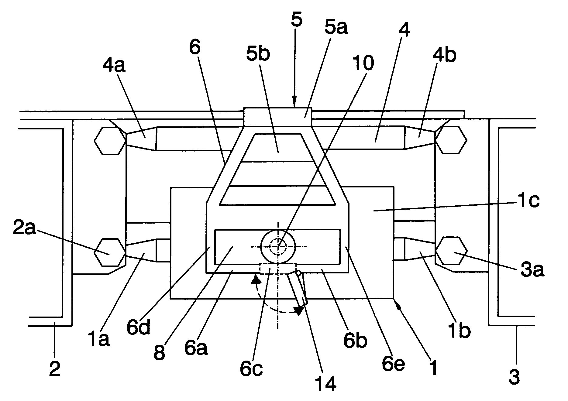
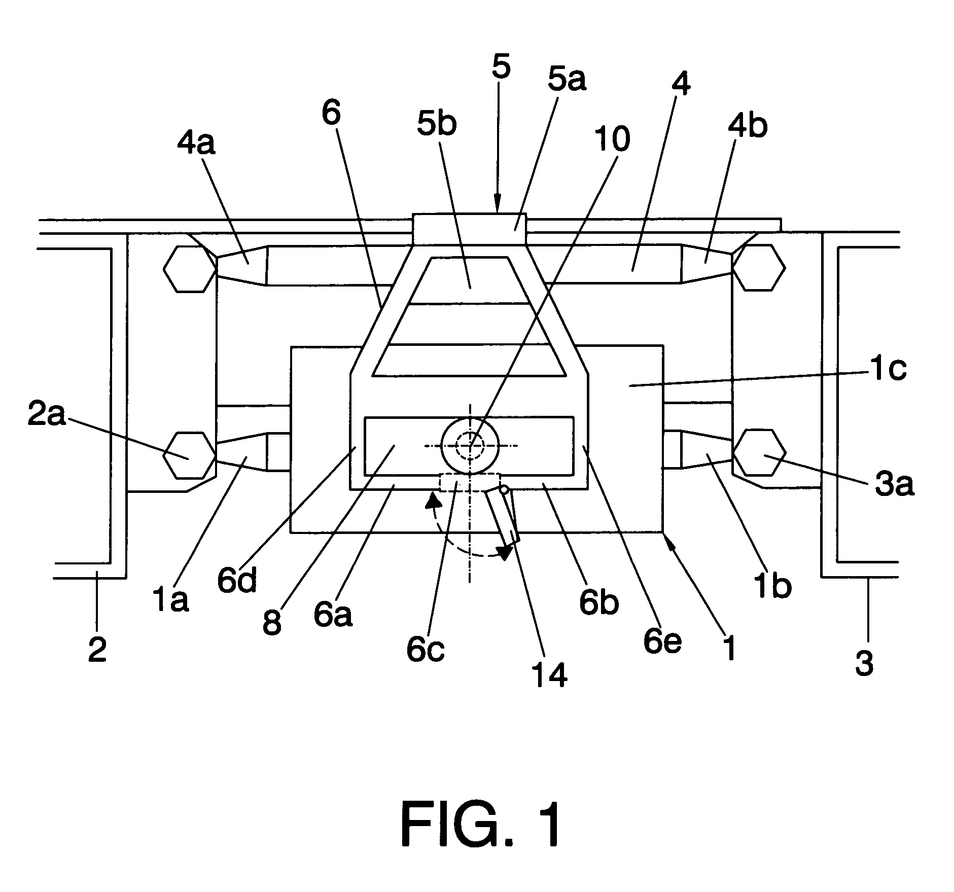
[0037]FIG. 1 is a schematic elevational side view showing the arrangement of the device of the present invention;

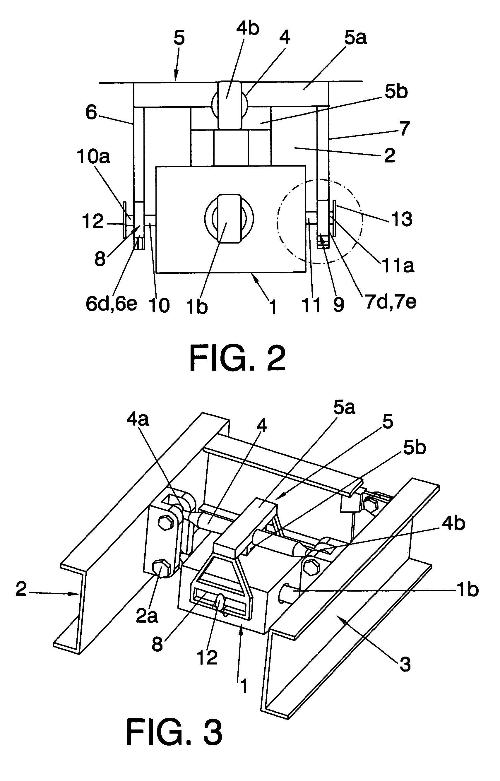
[0038]FIG. 2 is a schematic front view of the device shown in FIG. 1;

[0039]FIG. 3 is a schematic perspective view of the device shown in FIGS. 1 and 2;

[0040]FIG. 4 is a schematic side view of a first constructive alternative of the closing element applicable to the device of the present invention;

[0041]FIG. 5 is a schematic side view of a second constructive alternative of the closing element applicable to the device of the present invention;

[0042]FIG. 6 is a schematic cross-sectional view of the closing element shown in FIG. 5 according to the cross-line appearing in FIG. 5;

second embodiment

[0043]FIG. 7 is a schematic elevational side view showing the arrangement of the device of the present invention.

[0044]In these figures, references are used identifying the following elements:[0045]1 actuator[0046]1a first end part of the actuator[0047]1b second end part of the actuator[0048]1c first side part of the actuator[0049]1d second side part of the actuator[0050]2 first part[0051]2a first connection point of the actuator[0052]3 second part[0053]3a second connection point of the actuator[0054]4 reaction bar[0055]4a,4b ends of the reaction bar[0056]5 top part of the device[0057]5a main fitting[0058]5b secondary fitting[0059]6 first side arm[0060]6a, 6b converging sections[0061]6c open section[0062]6d first lateral section of the first side arm[0063]6e second lateral section of the first side arm[0064]7 second side arm[0065]7d first lateral section of the second side arm[0066]7e second lateral section of the second side arm[0067]8 window in the first side arm[0068]9 window in ...


PUM


Abstract

Safety attachment device for an actuator (1) attached at its ends respectively to a first and a second part (2, 3) which are connected to one another also by means of a reaction bar (4) which is located on the top of the actuator (1), said device comprises an upper part (5, 5a, 5b) immobilized on the reaction bar (4) and side arms (6, 7) which clasp the sides (1c, 1d) of the actuator (1), both having windows (8, 9) through which respective pins (10, 11) joined to these sides (1c, 1d) pass, the pin (10, 11) thus being situated without making contact with the edges of the window when the actuator is attached to the parts (2, 3), and each window (8, 9) being of a horizontal extension such that its side edges do not touch the pin (10, 11) which passes through said window (8, 9) when the actuator (1) is disconnected from any of the parts (2, 3).

Description

RELATED APPLICATIONS[0001]The present application claims priority from Spanish Patent Application Serial No. P200403172 and filed on Dec. 31, 2004. Applicant claims priority under 35 U.S.C. §119 as to said Spanish application, and the entire disclosure of that application is incorporated herein by reference.TECHNICAL FIELD OF THE INVENTION[0002]The present invention pertains to the field of the actuators which actuate moving elements, particularly to the area of the safety devices intended for preventing such actuators from falling fully or in part in the case that any of the anchorings are accidentally disconnected, and particularly to those devices where the full or partial falling thereof may have a negative impact on the safety of the element on which the installation is made. The device of the present invention is applicable to those installations in which the body of the actuator is fixed to a structural element by means of a connection which allows a relative movement between...

Claims


Application Information

Patent Timeline
Patent Type & Authority Patents(United States)
IPC IPC(8): H01H3/02H01H3/14H01H35/00
CPCB64C13/42Y10T74/18056Y02T50/44B64C13/341Y02T50/40
Inventor MARTIN HERNANDEZ, AGUSTIN MARIANO
Owner AIRBUS OPERATIONS SL
Learn More