High-rigidity forceps tip assembly for active forceps and active forceps equipped with the same

Inactive Publication Date: 2007-09-25
THE UNIV OF TOKYO
View PDF6 Cites 213 Cited by
  • Summary
  • Abstract
  • Description
  • Claims
  • Application Information

AI Technical Summary

Benefits of technology

[0009]Therefore, according to the forceps tip assembly of the present invention, the forceps tip mounted on the supporting part can be swung toward an arbitrary direction. Moreover, for swinging the supporting part, back-and-forth movement of the coupling points between the three leg parts and the front end portions of the three back-and-forth moving members is transmitted to the supporting part via the three leg parts which extend in parallel with a movement direction of the coupling points when the supporting part is at the foregoing reference position. Thus, a force applied to the supporting part fm the leg parts in the swinging of the supporting part is in a direction of pushing / pulling the leg parts. Consequently, rigidity of supporting the forceps tip by the supporting part can be increased.
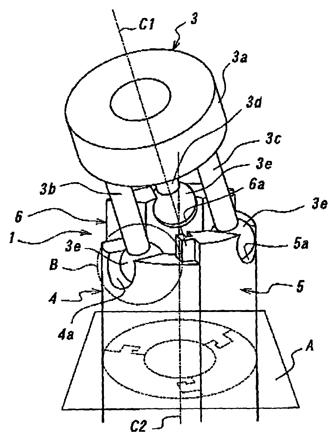
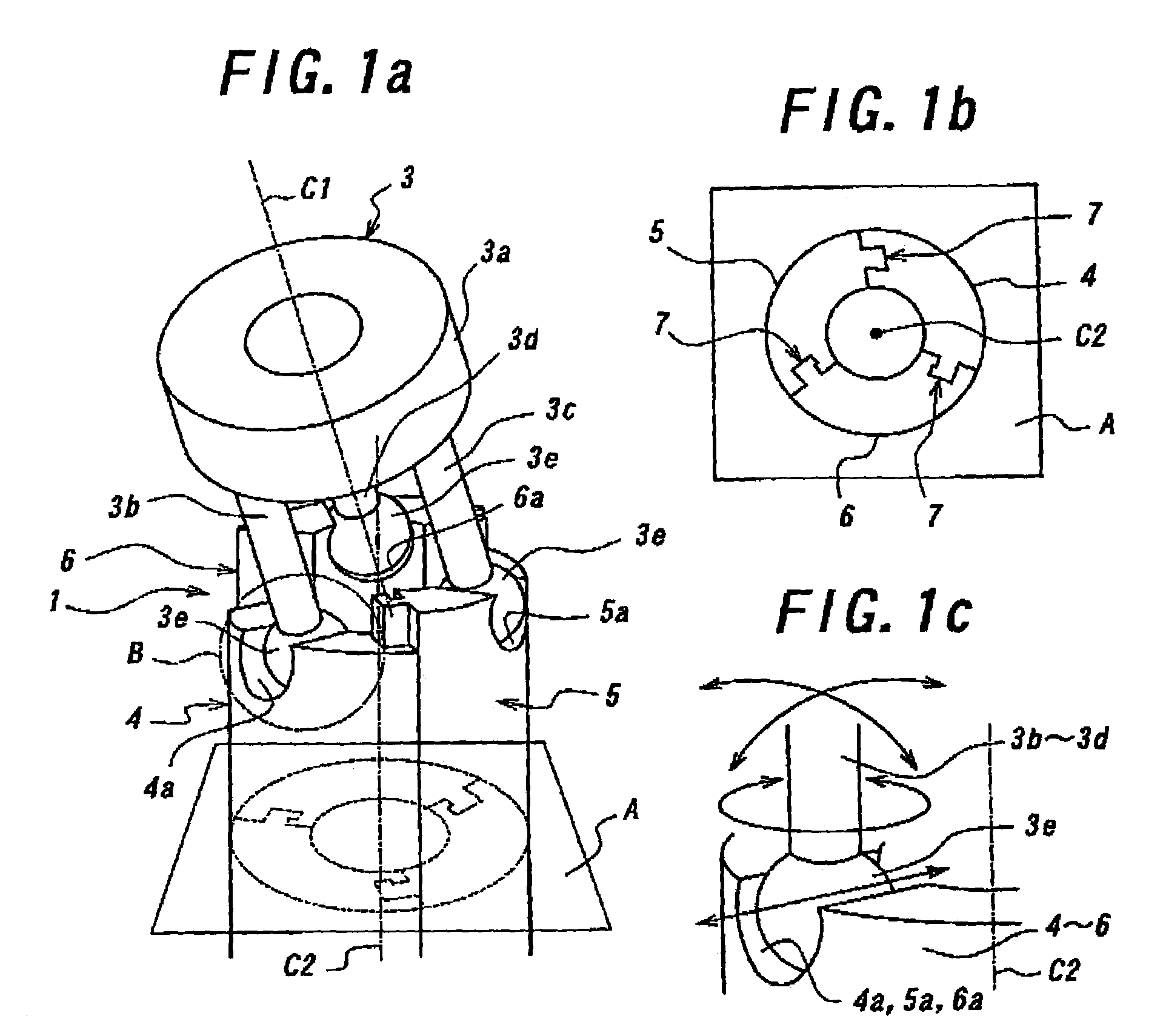
[0010]Note that, according to the present invention, spheres formed in respective rear end portions of the three leg parts and cylindrical grooves which are formed in the respective front end portions of the three back-and-forth moving members and extend in the direction orthogonal to the predetermined central axis line may be engaged with each other as swingable and slidable. By this swingable and slidable engagement, the three leg parts may be coupled with the front end portions of the three back-and-forth moving members at swingable and as slidable in the direction orthogonal to the predetermined central axis line, respectively. With such a constitution, the engagement structure includes the spheres and the cylindrical grooves, and thus the number of movable components can be reduced. Also in this regard, the rigidity of supporting the forceps tip can be increased. Moreover, the engagement structure can be formed by easily fabricating those movable components.
[0011]Moreover, according to the present invention, the supporting part may be formed of a ring-shaped member with such a constitution, by fitting or screwing the forceps tip into a center hole of the ring-shaped supping part, the forceps tip can be easily mounted on the supporting part. Moreover, a link member for opening / closing the forceps tip can be inserted into the center hole of the supporting part and thus the forceps tip can be opened and closed strongly by the link member while minimizing the width of the forceps tip assembly.
[0012]Furthermore, according to the present invention, the three back-and-forth moving members may be coupled with each other as relatively movable in the front-to-rear direction by use of grooves and ribs. The groove and rib may form a hook-shaped cross section, which are engaged with each other as slidable in the front-to-rear direction and are hooked up with each other in a direction intersecting with the front-to-rear direction. With such a constitution, the three back-and-forth moving members are coupled with each other with high rigidity. Thus, the forceps tip can be allowed to have high rigidity with a simple constitution.
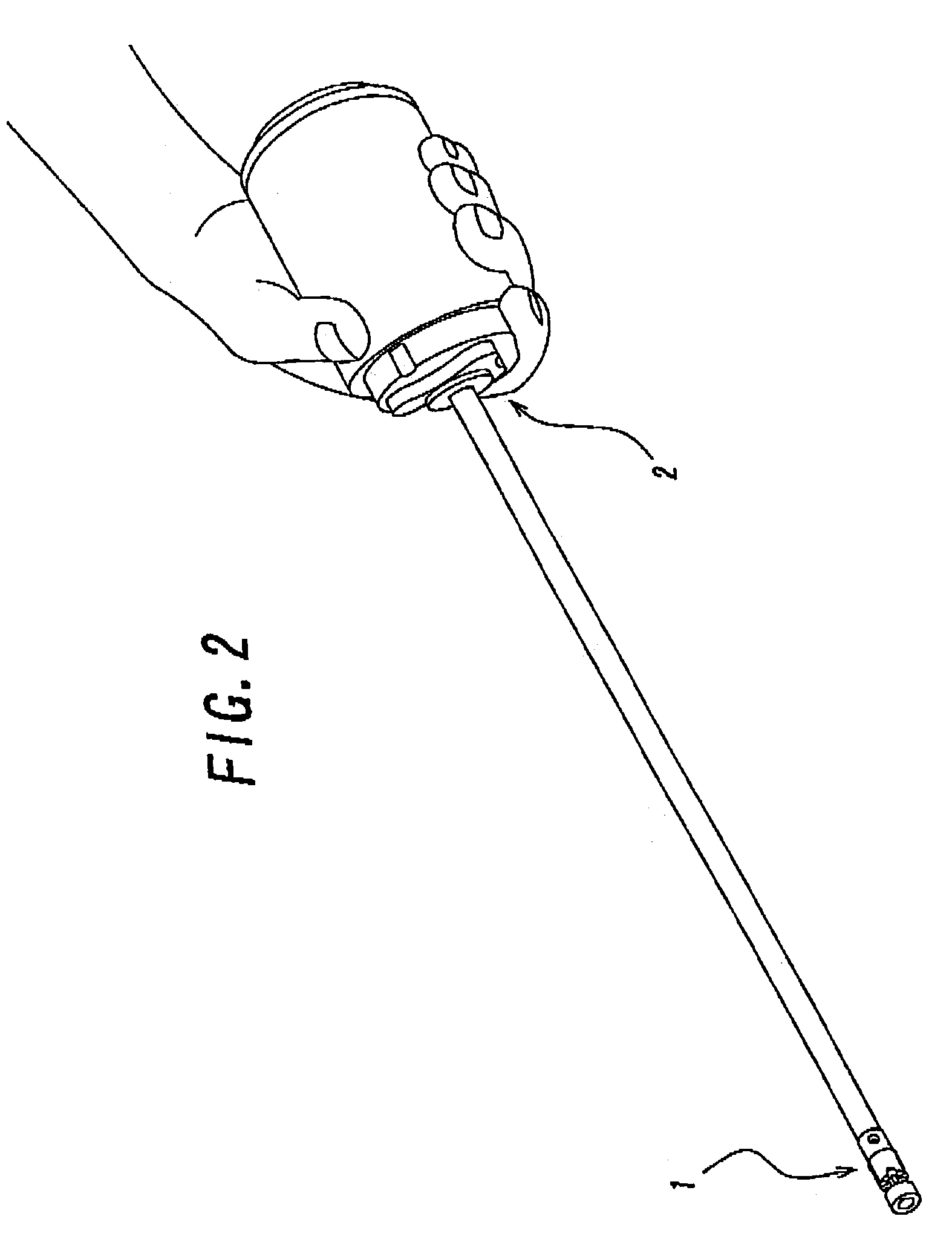
[0015]Therefore, according to the active forceps of the present invention, as described above, the forceps tip assembly supports the forceps tip with high rigidity, the driving means transmits a driving force to the forceps tip via the link mechanism, and thus the direction of the forceps tip can be changed. Consequently, the driving force can be efficiently transmitted to the forceps tip and the forceps tip can have rigidity higher than that of a wire driven one. Accordingly, the active forceps can be utilized for an operation which requires strength in the forceps tip, which includes, for example, an organ removal surgery and the like. Moreover, on the forceps tip side than the forceps base part, there merely exist, primarily, the back-and-forth moving members, the supporting part, the leg parts and the forceps tip, and if necessary, linking members which integrally link the back-and-forth moving members with the base part side back-and-forth moving members. Thus, the part at the forceps tip side can be easily made to have a smaller diameter. Consequently, the active forceps enables a minimally invasive surgery in surgeries such as the organ removal surgery accompanied by an operation requiring strength in the forceps tip.

Problems solved by technology

In the wire driven active forceps, even if the actuator has a large driving force, a wire may be elongated or cut off because of low rigidity and durability of the wire.
Thus, it is difficult to transmit a large force up to the forceps tip.
Consequently, the conventional wire driven active forceps described above was inappropriate for the organ removal surgery.

Method used


Image

  • High-rigidity forceps tip assembly for active forceps and active forceps equipped with the same
  • High-rigidity forceps tip assembly for active forceps and active forceps equipped with the same
  • High-rigidity forceps tip assembly for active forceps and active forceps equipped with the same

Examples


Embodiment Construction

[0024]With reference to the drawings, embodiments of the present invention will be described in detail below. Herein, FIG. 1a is a perspective view showing an embodiment of a high-rigidity forceps tip assembly for an active forceps according to the present invention, FIG. 1b is a cross-sectional view along the plane A in FIG. 1a and FIG. 1c is an explanatory view showing an operation of the part B in FIG. 1a. Moreover, FIG. 2 is a perspective view showing an embodiment of an active forceps of the present invention, which includes the forceps tip assembly of the foregoing embodiment. In the drawings, reference numeral 1 denotes the forceps tip assembly of the foregoing embodiment and reference numeral 2 denotes a forceps base part.

[0025]In the forceps tip assembly 1 of this embodiment, link driving is adopted as a driving system having high rigidity. In order to realize the link driving, the forceps tip assembly 1 of this embodiment includes a tripodal forceps tip supporting member 3...


PUM


Abstract

Provided is a forceps tip assembly capable of supporting a forceps tip with high rigidity in order to realize a laparoscopic surgery requiring a significant power with the forceps tip, such as an organ removal surgery which has been heretofore difficult to be performed by a robot for medical use. The forceps tip assembly includes: a forceps tip supporting member which has a supporting part for supporting a forceps tip and three leg parts which are disposed at even intervals in a circumferential direction around a central axis line C1 and fixed to the supporting part so as to protrude backward from the supporting part; and three back-and-forth moving members which are disposed at even intervals in a circumferential direction around a predetermined central axis line C2 extending in a front-to-rear direction, which have their front end portions coupled with the three leg pads swingably and slidably in a direction orthogonal to the predetermined central axis line C2 and which are mutually coupled together as relatively movable in the extending direction of central axis line C2.

Description

BACKGROUND OF THE INVENTION[0001]1. Field of the Invention[0002]The present invention relates to a high-rigidity forceps tip assembly for an active forceps used in a minimally invasive surgery and the like and to an active forceps including the same.[0003]2. Prior Art[0004]Conventional active forceps used in a master-slave robot for a minimally invasive surgery (particularly a laparoscopic surgery) is mostly ones that change a direction of a forceps tip by wire driving (for example, refer to Guthart G. S., and J. K. Salisbury, “The Intuitive Telesurgery System: Overview and Application.” Proc. of the IEEE International Conference on Robotics and Automation, San Francisco Calif., April 2000). This is because a small mechanism of changing a direction of a forceps by transmitting a driving force to a forceps tip from an actuator disposed in a base of the forceps can be relatively easily realized by use of the wire driving.[0005]In the wire driven active forceps, even if the actuator ha...

Claims


Application Information

Patent Timeline
IPC IPC(8): B25J17/02A61B17/28A61B1/00B25J17/00A61B19/00
CPCA61B19/22A61B2017/2927Y10T74/20329Y10T74/20335A61B2019/2226A61B34/70A61B2034/304
Inventor NAKAMURA, YOSHIHIKOOKADA, MASAFUMICHIYODA, SHINGO
Owner THE UNIV OF TOKYO
Why Eureka
Try Eureka