Liquid crystal display device protection structure for electronic equipment
a technology of electronic equipment and display device, which is applied in the direction of instruments, portable computer details, electrical apparatus casings/cabinets/drawers, etc., can solve the problems of cracks, unfavorable mobile phone expansion, and increased outline shape size, etc., and achieves the effect of convenient fixation
- Summary
- Abstract
- Description
- Claims
- Application Information
AI Technical Summary
Benefits of technology
Problems solved by technology
Method used
Image
Examples
first embodiment
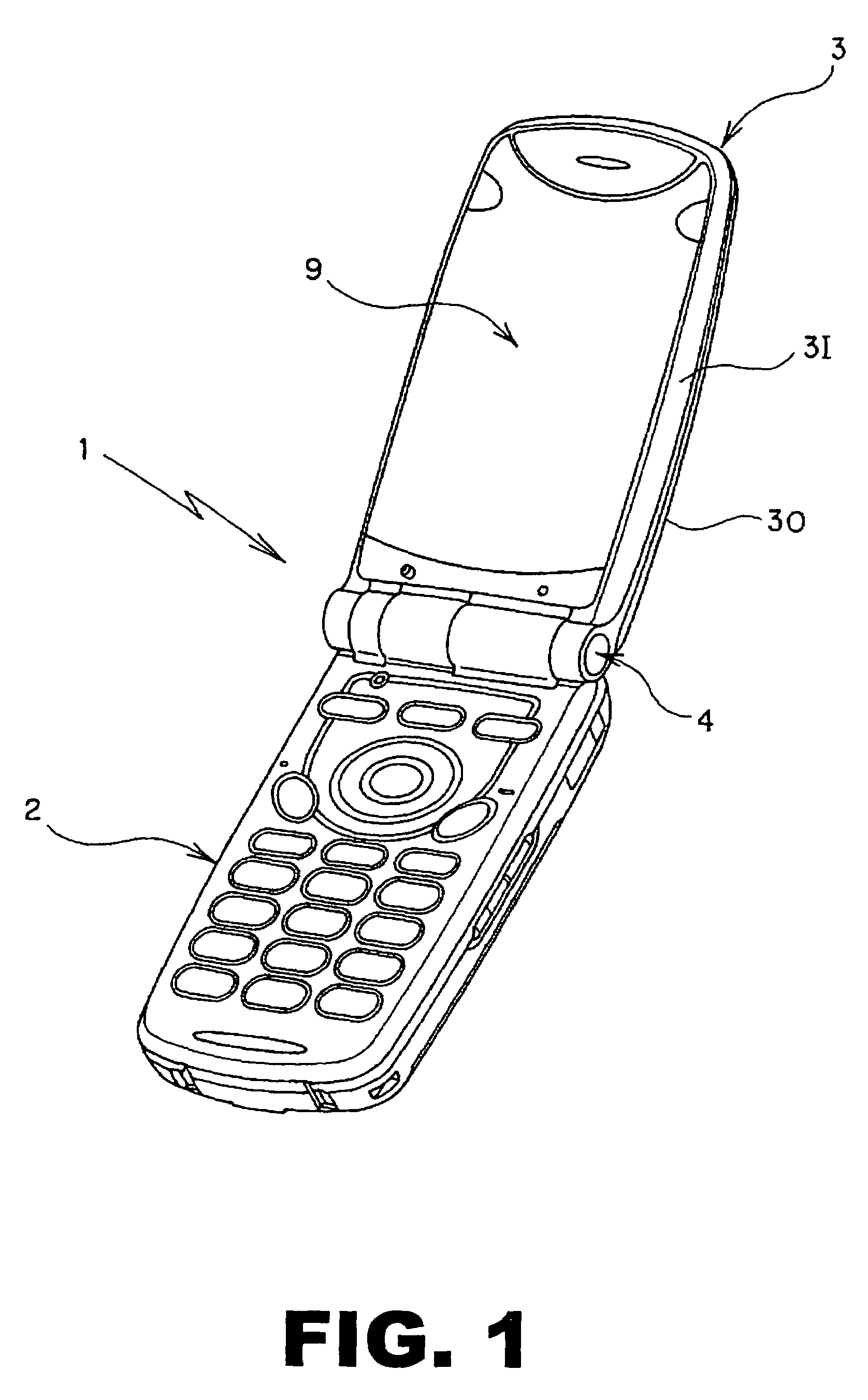
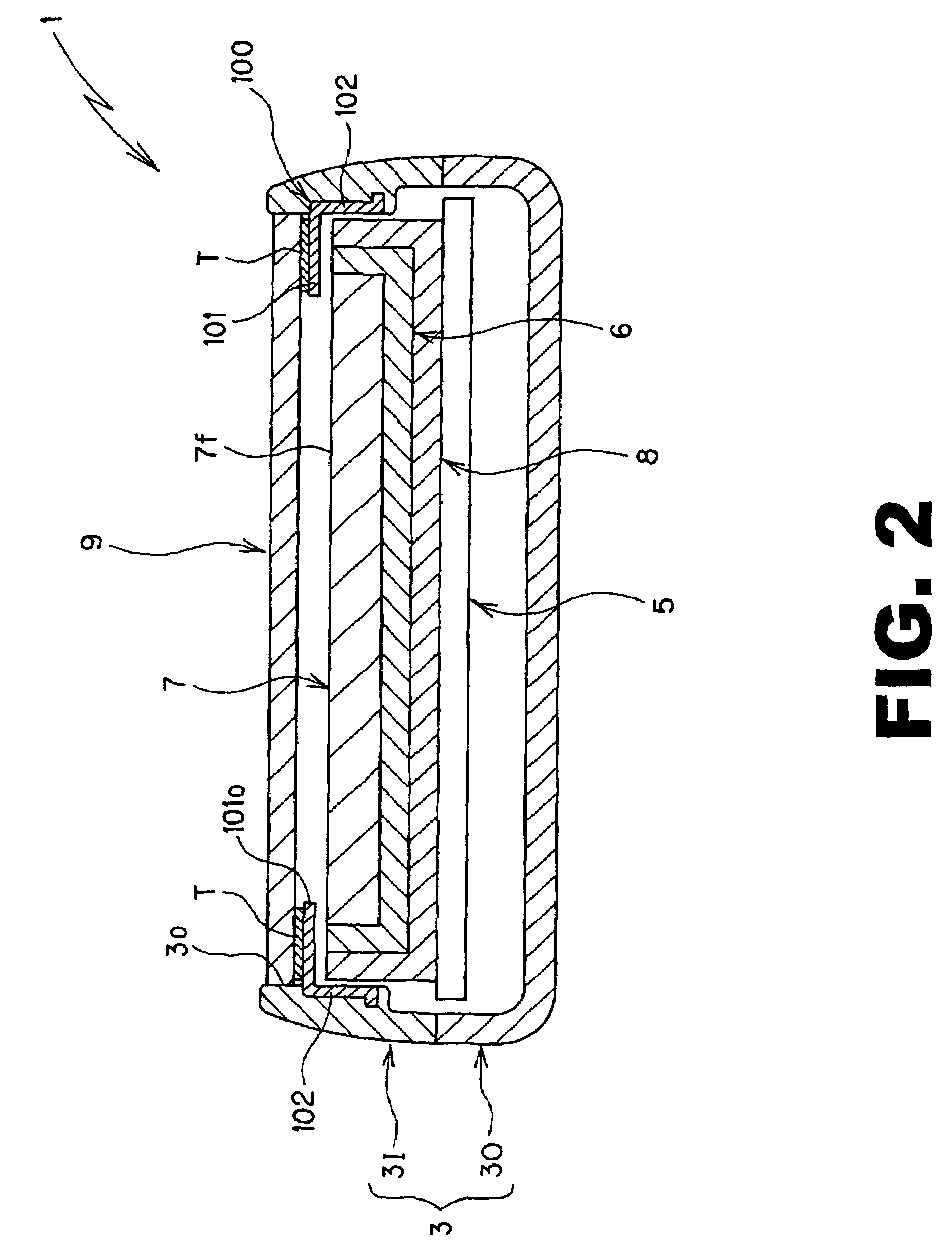
[0058]FIG. 1 through FIG. 6 show a first embodiment where a liquid crystal display device protection structure relating to the present invention is applied to a foldable mobile phone, which is a type of electronic equipment. This mobile phone 1 comprises a lower cabinet 2 provided with a variety of controllers, and an upper cabinet 3 accommodating a liquid crystal display device 7 later described. The lower cabinet 2 and the upper cabinet 3 are connected to each other through a hinge 4 such that the foldable mobile phone can be freely opened and closed.
[0059]The upper cabinet 3, which constitutes the equipment cabinet together with the lower cabinet 2, comprises an upper inner casing 3I and an upper outer casing 3O which are assembled to each other, and the upper inner casing 3I and the upper outer casing 3O are both manufactured in a desired shape by injection molding of plastic material.
[0060]As shown in FIG. 2 and FIG. 3, a circuit board 5 is accommodated in the inside of the upp...
second embodiment
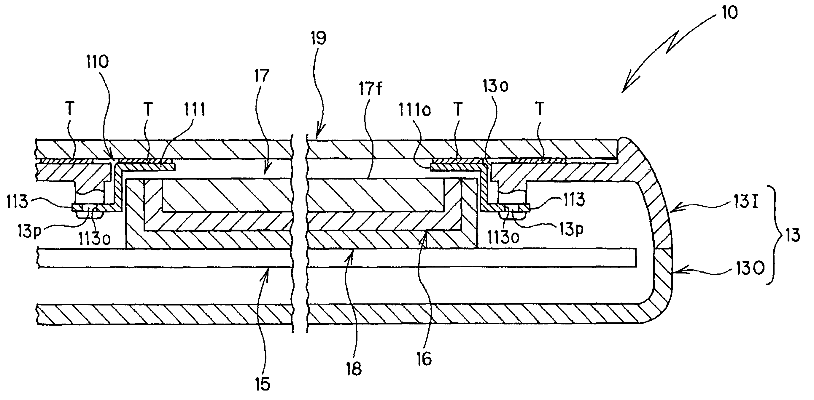
[0075]FIG. 7 to FIG. 12 show a second embodiment where a liquid crystal display device protection structure relating to the present invention is applied to a mobile phone, which is a type of electronic equipment. An upper cabinet (equipment cabinet) 13 in the foldable mobile phone 10 comprises an upper inner casing 13I and an upper outer casing 13O which are assembled to each other, and the upper inner casing 13I and the upper outer casing 13O are both manufactured in a desired shape by injection molding of plastic material.
[0076]As shown in FIG. 7 to FIG. 9, a circuit board 15 is accommodated in the inside of the upper cabinet 13, and on the component mounting surface of the circuit board 15, a backlight device 16 and a liquid crystal display device 17 constituting a liquid crystal display unit are mounted in a prescribed location through a holder 18.
[0077]In the upper inner casing 13I of the upper cabinet 13 is formed a viewing window 13o which is faced with the display screen 17f...
third embodiment
[0086]FIG. 13 to FIG. 18 show a third embodiment where a liquid crystal display device protection structure relating to the present invention is applied to a mobile phone, which is a type of electronic equipment. An upper cabinet (equipment cabinet) 23 in this foldable mobile phone 20 comprises an upper inner casing 23I and an upper outer casing 23O which are assembled to each other. The upper inner casing 23I and the upper outer casing 23O are both manufactured in a desired shape by injection molding of plastic material.
[0087]As shown in FIG. 13 to FIG. 15, a circuit board 25 is accommodated in the inside of the upper cabinet 23. On the component mounting surface of the circuit board 25, a backlight device 26 and a liquid crystal display device 27 constituting a liquid crystal display unit are mounted in a prescribed location through a holder 28.
[0088]In the upper inner casing 23I of the upper cabinet 23 is formed a viewing window 23o which is faced with the display screen 27f of t...
PUM
| Property | Measurement | Unit |
|---|---|---|
| mechanical strength | aaaaa | aaaaa |
| weight | aaaaa | aaaaa |
| thickness | aaaaa | aaaaa |
Abstract
Description
Claims
Application Information
 - R&D
- Intellectual Property
- Life Sciences
- Materials
- Tech Scout
- Unparalleled Data Quality
- Higher Quality Content
- 60% Fewer Hallucinations
Browse by: Latest US Patents, China's latest patents, Technical Efficacy Thesaurus, Application Domain, Technology Topic, Popular Technical Reports.
© 2025 PatSnap. All rights reserved.Legal|Privacy policy|Modern Slavery Act Transparency Statement|Sitemap|About US| Contact US: help@patsnap.com


