Compact lighting system attachable to a surgical tool and method of use thereof

a compact, lighting system technology, applied in the field of compact lighting system, can solve the problems of difficulty in obtaining adequate, clear, safe lighting of the operation site, difficulty in obtaining the freedom of movement, mounting a light source on the forehead of the surgeon, etc., and achieve the effect of convenient attachmen

Active Publication Date: 2007-09-18
LUMENXT LLC
View PDF5 Cites 37 Cited by
  • Summary
  • Abstract
  • Description
  • Claims
  • Application Information

AI Technical Summary

Benefits of technology

[0006]It is a principal object of the present invention to provide a lightweight, compact, self-powered, safely operable lighting system that can be readily attached to a known surgical tool to provide prolonged, clear, consistent lighting at a surgical site.
[0007]Another object is to provide a surgeon with a lightweight, compact, safely operable lighting system that can be readily and securely mounted to a conventional surgical tool to provide clear, high intensity, white light at a surgical site in a confined region for prolonged operations.
[0008]A related object is to provide a lightweight, compact, self-powered, safely operable lighting system mountable to a known surgical tool to provide a surgeon clear, consistent, high intensity lighting within a selected wavelength range while ensuring that tissues contacted by any part of the lighting system will not suffer damage due to unacceptably high temperature.

Problems solved by technology

Surgeons operating in confined regions of a patient's body, e.g., in an ear, throat or vagina, often encounter difficulty in obtaining adequate, clear, safe lighting of the operational site—especially during prolonged operational procedures.
The mounting of a light source on a surgeon's forehead, light sources manipulated by an assistant, and other known solutions generally are not satisfactory—especially where avoidance of shadowing and correct angle of incidence are important considerations.
Neither is the provision of a light source mounted to the surgeon's wrist or finger, or even on the surgical tool itself, if the lighting elements are bulky or if either the lighting or electrical power is conveyed by trailing fiber-optic cables, wires or other arrangements that tend to limit the surgeon's freedom of movement or might become entangled where multiple light sources are required.
Furthermore, the provision of clear white light of sufficient intensity for periods exceeding more than a few minutes poses the problem that portions of the lighting system may attain unacceptably high local temperatures and may accidentally cause tissue damage to either the patient or to members of the surgical team.
Another concern always present if oxygen is being supplied to the patient is the danger of igniting materials contacted by the hot light source.

Method used


Image

  • Compact lighting system attachable to a surgical tool and method of use thereof
  • Compact lighting system attachable to a surgical tool and method of use thereof
  • Compact lighting system attachable to a surgical tool and method of use thereof

Examples


first embodiment

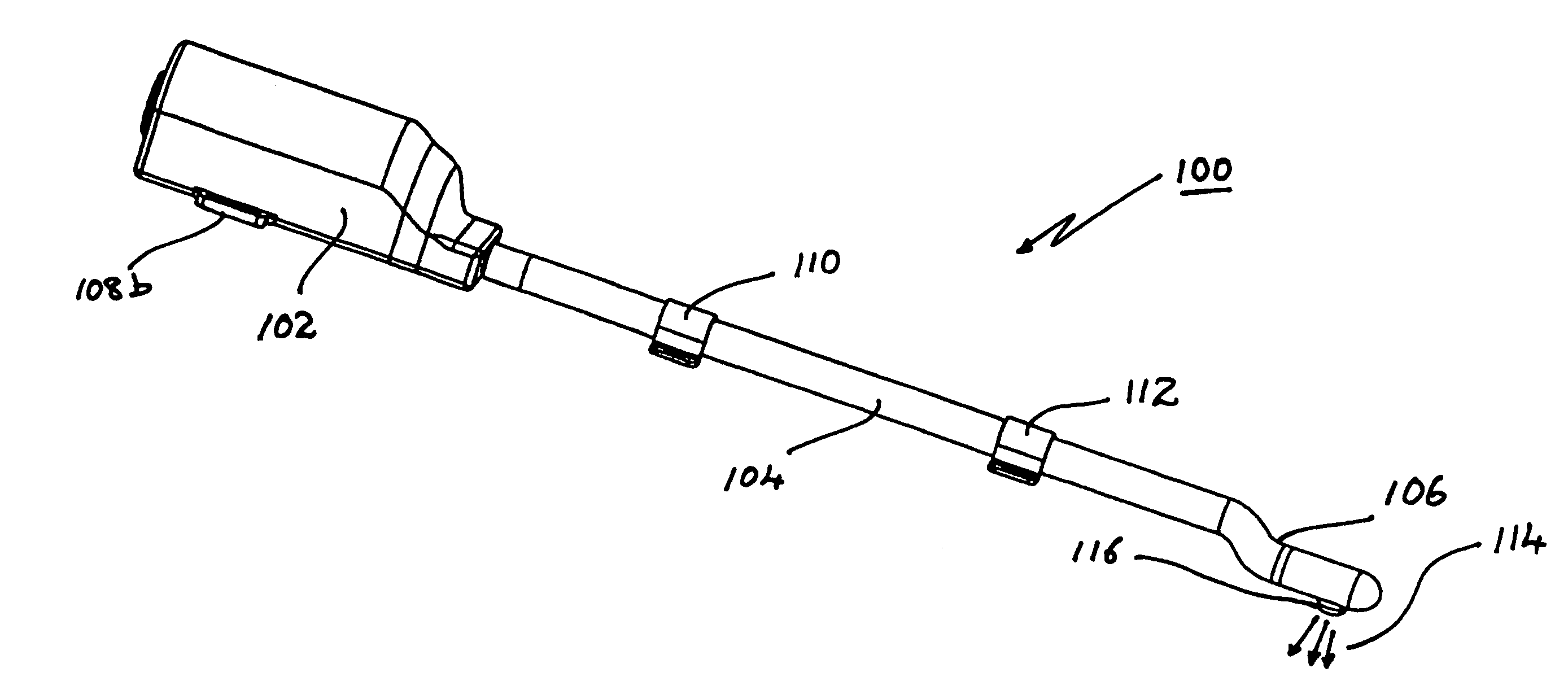
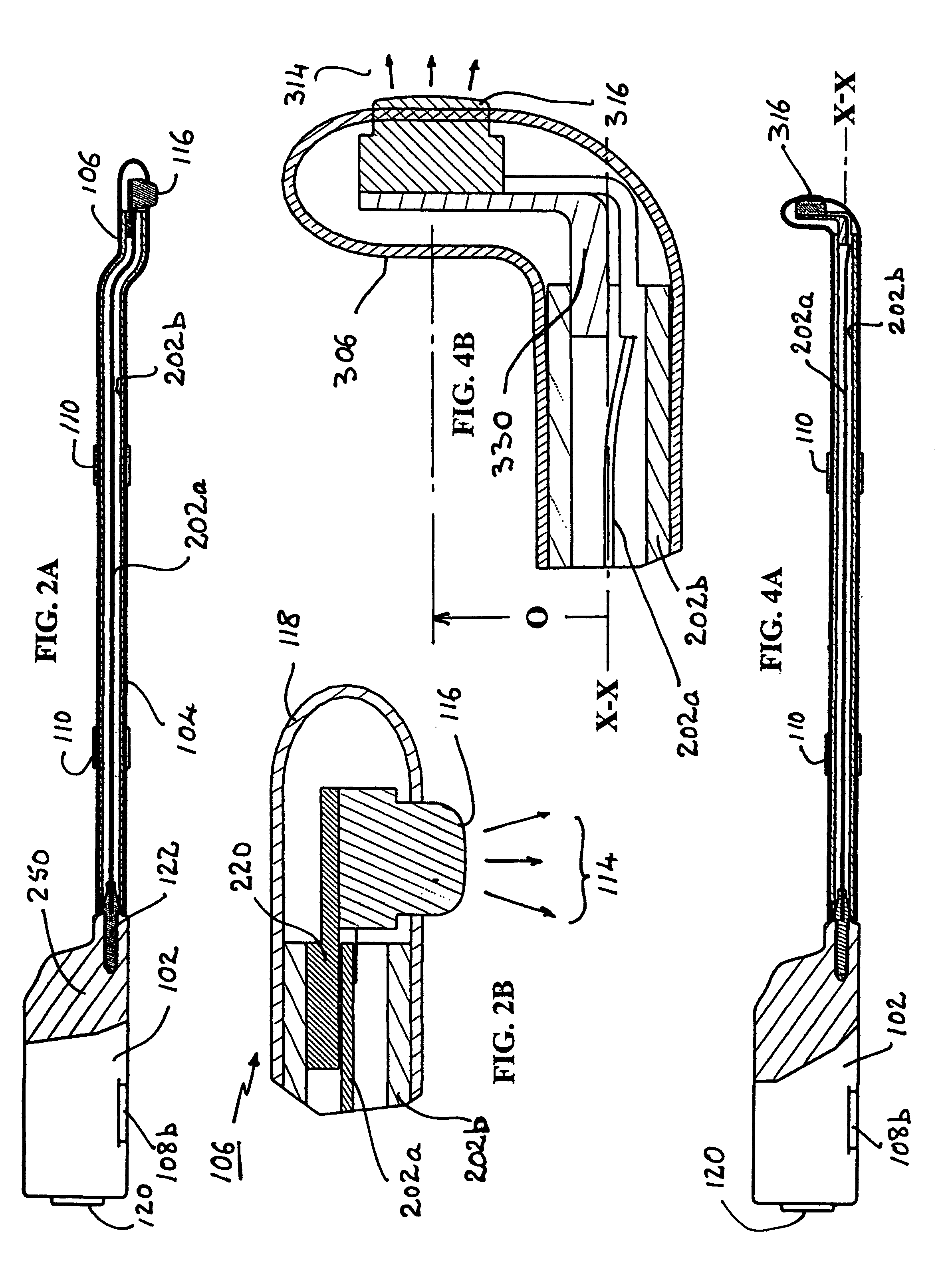
[0039]Light-emitting element 106 in the first embodiment is of side-lighting kind, i.e., light 114 is emitted sideways relative to the body of the light-emitting element itself from a light source 116 mounted within, access to the inside being available upon removal of sealing element 118 in front.

[0040]Power unit 102, likewise, has internal components that may be accessed upon removal of a sealing cap 120 at the rear or at any other convenient location on the body of power unit 102. This cap 120 may be made of a flexible electrically insulating material such as a plastic, and will then allow the user to operate a conventional on-off switch (not shown) that can be actuated by pressure applied there.

[0041]The entire lighting system structure may be assembled by conventional friction-or force-fitting of the power unit to the connection element and similar fitting of the latter to the light-emitting element body. Small flexible “O-rings” or the like may be used as gaskets at the respec...

second embodiment

[0054]FIGS. 5A-5E depict in various views just how the lighting system 300 may be used in combination 500 with a conventional suction or aspiration tool 502 of a kind frequently employed during surgery. Particularly noteworthy is the optional provision of arrangement 504 comprising a set of alternating ridges (or flutes) 506 and grooves 508 at the proximal end of the suction tool body to prevent relative rotation between the lighting system and the suction tool. The base portion of the power unit can be configured for this in obvious manner to cooperate with the selected shape of the suction tool in the attachment region. This would make possible the provision of a set of surgical tools having different functions but all having comparable mounting portions at which a particular model of the lighting system could be attached. This would also ensure user-convenience in that the surgeon will experience essentially the same kind of grip regardless of the tool in use.

[0055]Alternative at...


PUM


Abstract

A compact, self-contained lighting system is attachable to a surgical tool to enable a user to selectively direct light at a site where the tool is to be applied. The system has a power unit that may contain rechargeable power cells, a malleable electrical connection element, and a light-emitting element powered thereby to emit high intensity white light, preferably from an LED. The system ensures against tissue damage due to inadvertent overheating by continuously removing byproduct heat from the light-emitting element, via the connection element, to the power unit with portions of each of these components serving as respective heat sinks and / or as thermal conduits to facilitate this process. The removed heat is dissipated to the ambient atmosphere, the surgical tool and even the user, and permits safe prolonged operations in confined regions of a patient's body.

Description

FIELD OF THE INVENTION[0001]This invention relates to a lightweight, compact lighting system configured to be readily attachable to a hand-held surgical tool to provide lighting of a surgical site during use of the tool. More particularly, the invention relates to a lightweight, compact, self-powered, optionally modular to be partially reusable, lighting system that can be readily attached to any of a variety of known hand-held surgical tools to provide the user clear, consistent and selectively directed white lighting of a surgical site at which the tool is to be applied. Heat incidental to generation of light is removed away from the light-generating portion of the lighting system to ensure safe prolonged operation.BACKGROUND OF THE RELATED ART[0002]Surgeons operating in confined regions of a patient's body, e.g., in an ear, throat or vagina, often encounter difficulty in obtaining adequate, clear, safe lighting of the operational site—especially during prolonged operational proce...

Claims


Application Information

Patent Timeline
Patent Type & Authority Patents(United States)
IPC IPC(8): F21S2/00
CPCA61B19/52A61B2019/521Y10S362/804A61B90/36A61B2090/309
Inventor HORRELL, ROBIN S.BIBELHAUSEN, DAVIDKARRAM, MICKEY M.LOVE, JOHN F.
Owner LUMENXT LLC
Why Eureka
Try Eureka