
Non-coherent frequency shift keying transmitter using a digital interpolation synthesizer

a technology of interpolation synthesizer and frequency shift keying, which is applied in the direction of digital transmission, modulation, pulse technique, etc., can solve the problems of power consumption, relative long period, and neither satisfying the quality of the signal transmitted by the modulator

Inactive Publication Date: 2007-09-11
NOVATEK MICROELECTRONICS CORP
View PDF8 Cites 7 Cited by
  • Summary
  • Abstract
  • Description
  • Claims
  • Application Information

AI Technical Summary

Benefits of technology

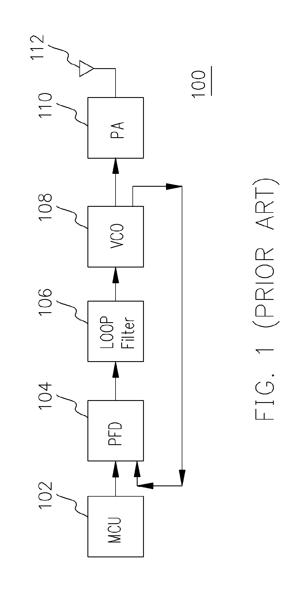
[0008]An object of the present invention is to avoid unnecessary analog circuits and use succinct analog circuits to implement the PLL in the transmitter.
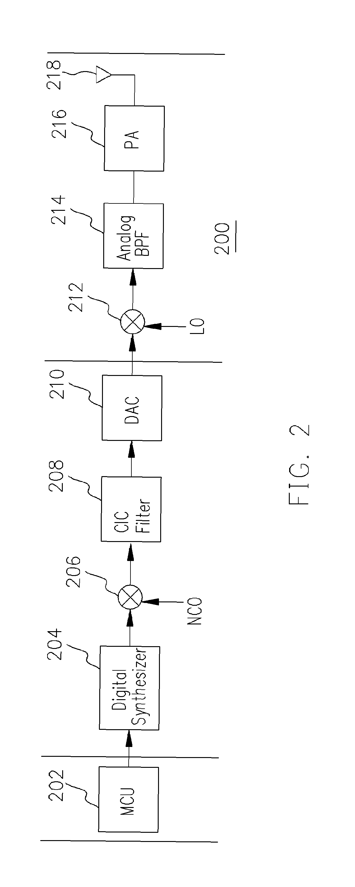
[0013]In the present invention, a digital frequency synthesizer is used to replace a portion of analog circuits. Hence, the fabrication migration would be reduced during the fabrication of the circuits. Further, the modulated RF signal is more stable than that of the conventional modulator, has a more efficient spectrum control, and has a better performance for the receiver.
[0014]In addition, the present invention uses digital interpolation synthesizer. Compared to the transmitting signal generated by a conventional analog PLL, the transmitting signal of the present invention is more stable; i.e., within the same frequency band of the spectrum, the utilization rate of the spectrum is much higher. Further, the performance on the receiver side is much better.

Problems solved by technology

First, the PLL requires a relatively long period for settling time to transmit a precise frequency and thus it is power consuming.
Further, the quality of the signal transmitted by the modulator is neither satisfying.
Further, the modulator suffers from fabrication migration thus transmission quality is degraded for limitation of PLL bandwidth.

Method used


Image

  • Non-coherent frequency shift keying transmitter using a digital interpolation synthesizer
  • Non-coherent frequency shift keying transmitter using a digital interpolation synthesizer
  • Non-coherent frequency shift keying transmitter using a digital interpolation synthesizer

Examples


Embodiment Construction

[0018]FIG. 2 is a block diagram of a non-coherent FSK modulator 200 in accordance with a preferred embodiment of the present invention. The non-coherent FSK modulator 200 includes a micro processing unit 202, a digital synthesizer 204, a numerical controlled oscillator (NCO) 206, a cascaded integrator-comb (CIC) filter 208, a digital-analog (D / A) converter 210, a local oscillator 212, a band-pass filter 214, a power amplifier 216, and a transmitting end 218. The digital synthesizer 204, the numerical controlled oscillator (NCO) 206, the cascaded integrator-comb (CIC) filter 208, and the digital-analog (D / A) converter 210 are deemed to be an intermediate frequency processor. The local oscillator 212, the band-pass filter 214, the power amplifier 216, and the transmitting end 218 are deemed to be a radio frequency processor. The micro processing unit 202 receives the baseband signal and generates a digital signal sequence corresponding to the baseband signal inputting to the intermedi...


PUM


Abstract

A non-coherent frequency shift keying transmitter for up-converting a baseband signal to a radio frequency signal is provided. The non-coherent frequency shift keying transmitter applies the interpolation method in a digital frequency synthesizer to replace the conventional Phase Locked Loop (PLL) circuit. The micro processing unit receives a baseband signal firstly, then the baseband signal is converted to a RF signal via a digital synthesizer, a numerical controlled oscillator, a cascaded integrator-comb filter, and a digital-analog converter. The RF signal is then transmitted via a local oscillator, a band-pass filter, a power amplifier, and a transmitting end. This circuit eliminates unnecessary analog devices so that fabrication migration issue is avoided. Further, the modulated RF signal is more stable than that of the conventional modulator, and has a more efficient spectrum control and a better performance on the receiver end. A non-coherent FSK transmitting system is also provided in the present invention.

Description

CROSS REFERENCE TO RELATED APPLICATIONS[0001]This application claims the priority benefit of Taiwan application serial no. 92124167, filed Sep. 2, 2003.BACKGROUND OF INVENTION[0002]1. Field of the Invention[0003]This invention generally relates to a non-coherent frequency shift keying transmitter, and more particularly to a non-coherent frequency shift keying transmitter using a digital interpolation synthesizer.[0004]2. Description of Related Art[0005]Digital wireless communication system, such as mobile phone communication system using bluetooth protocol, has been widely used by the consumers and becomes an indispensable tool for a modern daily life. In a digital wireless communication system, because of the high efficiency requirement for transmission, the non-coherent frequency shift keying (FSK) technology plays an important role in generating RF signals for carrying the transmitting signals.[0006]In a digital wireless communication system, a non-coherent FSK modulator includes...

Claims


Application Information

Patent Timeline
Patent Type & Authority Patents(United States)
IPC IPC(8): H04L27/10H03C3/00H04L27/12
CPCH03C3/00H04L27/122
Inventor SHIUNG, DAVID
Owner NOVATEK MICROELECTRONICS CORP
Learn More