
Logical star topologies for non-star networks

Active Publication Date: 2007-09-11
LUCENT TECH INC +1
View PDF2 Cites 22 Cited by
  • Summary
  • Abstract
  • Description
  • Claims
  • Application Information

AI Technical Summary

Benefits of technology

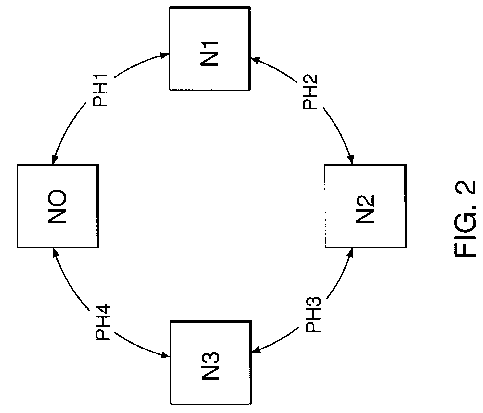
[0013]On the other hand, because the underlying physical network has a non-star topology, networks of the invention have fewer problems associated with traffic bottlenecks and single points of failure than physical star networks. In the case where the underlying network is a protected ring, for example, the resulting overlaid star network benefits from the robustness of the underlying ring while retaining the routing simplicity of a star.

Problems solved by technology

The greater the number of hops in a connection, the greater the total amount of such processing overhead for the connection.
One of the disadvantages of star networks is that the central node is involved in all network traffic.
As a result, as the number of connections in a star network increases, traffic bottlenecks are more and more likely to occur at the central node.
Another disadvantage of star networks is that the central node corresponds to a potential single point of failure for the entire network.
On the other hand, a star topology is not generally suitable for the backbone of a service provider network, because it creates both a bottleneck and a single point of failure.
On the other hand, one of the disadvantages of ring networks as compared to star networks is that the minimum distance between two nodes on diametrically opposing sides of an n-node ring network is n / 2 hops.
As such, as the number of nodes in a ring network increases, the average amount of processing overhead per network connection also increases.

Method used


Image

  • Logical star topologies for non-star networks
  • Logical star topologies for non-star networks
  • Logical star topologies for non-star networks

Examples


Embodiment Construction

[0029]Reference herein to “one embodiment” or “an embodiment” means that a particular feature, structure, or characteristic described in connection with the embodiment can be included in at least one embodiment of the invention. The appearances of the phrase “in one embodiment” in various places in the specification are not necessarily all referring to the same embodiment, nor are separate or alternative embodiments mutually exclusive of other embodiments.

[0030]According to embodiments of the invention, a logical star topology is overlaid on an underlying non-star network, such as a ring network. Depending on the particular implementation, the underlying ring topology may correspond to the topology of the actual physical network or it may itself correspond to a logical ring topology overlaid on a further underlying non-ring (and non-star) network. In theory, the invention may involve the sequential overlaying of one or more logical topologies on top of the ultimate, actual physical ...


PUM


Abstract

A logical star architecture imposed on an underlying non-star network, for example a Virtual Path Ring (VPR), enhances a mesh protocol with an automatic method for Virtual Path ID (VPI) generation. The VPIs are used by the mesh protocol's inherent routing function to effect automatic configuration at installation, automatic reconfiguration at node updates, and automatic reconfiguration for protection switching. The imposition of the logical star architecture on a VPR reduces node-to-node switching costs (e.g., delay, as well as memory and processing costs) since all nodes in a logical star topology are at most two logical hops away. The logical star also conserves virtual path address space relative to a fully configured ring. Additionally, the imposition of the logical star architecture allows existing star functions to be deployed on the underlying network. Finally, when the underlying architecture is a ring, the protection advantages of ring networks can be preserved.

Description

BACKGROUND OF THE INVENTION[0001]1. Field of the Invention[0002]The invention relates to routing signals through communication networks.[0003]2. Description of the Related Art[0004]A star network is a network of nodes having a topology in which one of the nodes (called “the central node”) is directly connected to every other node in the network, while each of those other nodes is directly connected only to the central node.[0005]One advantage of star networks is that traffic can be transmitted between any two nodes in the network with at most two “hops,” where a hop is defined as transmission between two directly connected nodes. For every hop in a connection, the node at the beginning of the hop performs a certain amount of signal processing to route the signal towards the node at the end of the hop. The greater the number of hops in a connection, the greater the total amount of such processing overhead for the connection. From the perspective of minimizing processing overhead and ...

Claims


Application Information

Patent Timeline
IPC IPC(8): H04L12/28H04L12/56H04L12/44
CPCH04L12/44
Inventor BAKER, ALBERT D.
Owner LUCENT TECH INC
Learn More