
Electronic module

a technology of electronic modules and modules, applied in the direction of electrical apparatus casings/cabinets/drawers, inorganic insulators, coupling device connections, etc., can solve the problem that the height of electronic modules cannot be increased arbitrarily, and achieve the effect of cleaning the area

Inactive Publication Date: 2007-09-04
IMF ELECTRONIC GMBH
View PDF6 Cites 9 Cited by
  • Summary
  • Abstract
  • Description
  • Claims
  • Application Information

AI Technical Summary

Benefits of technology

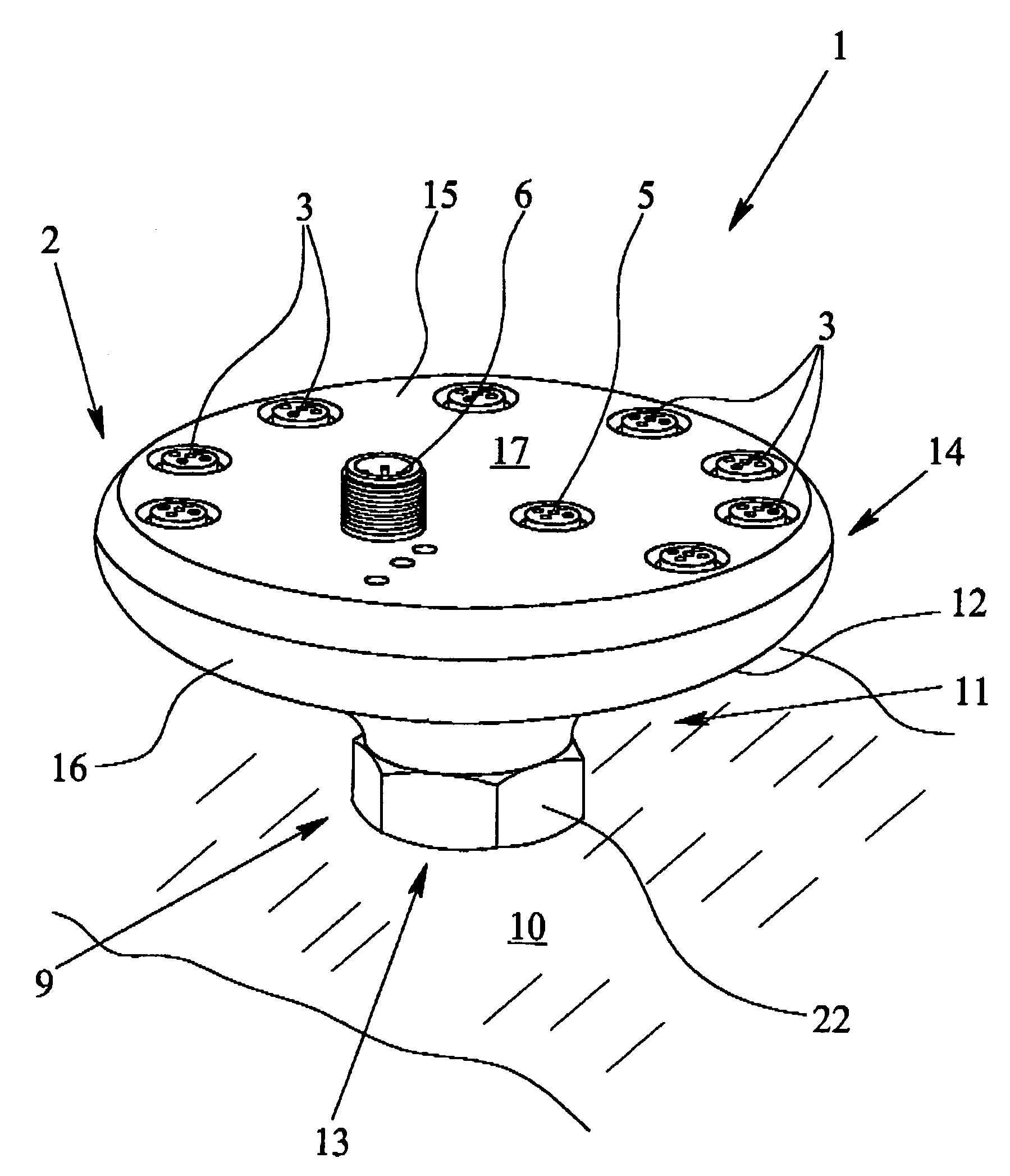
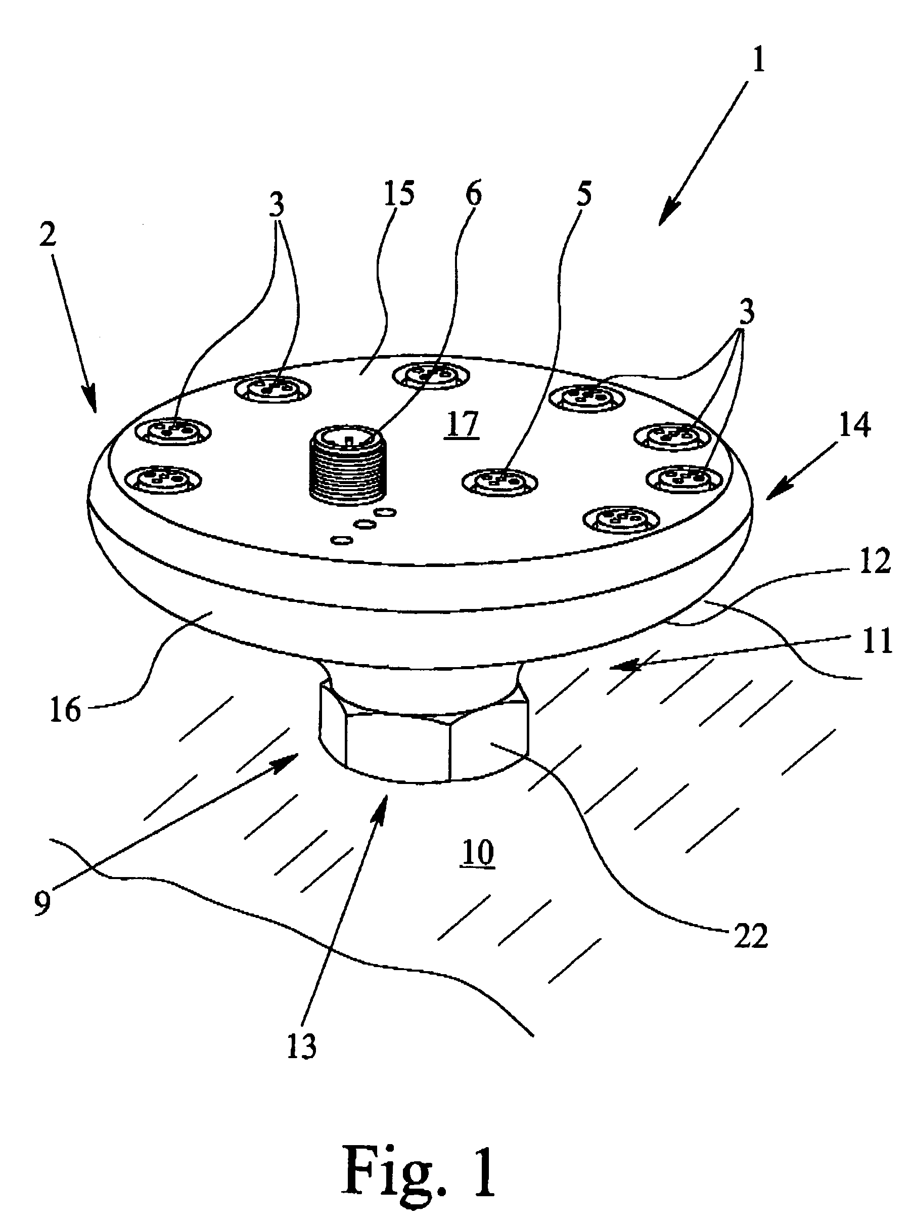
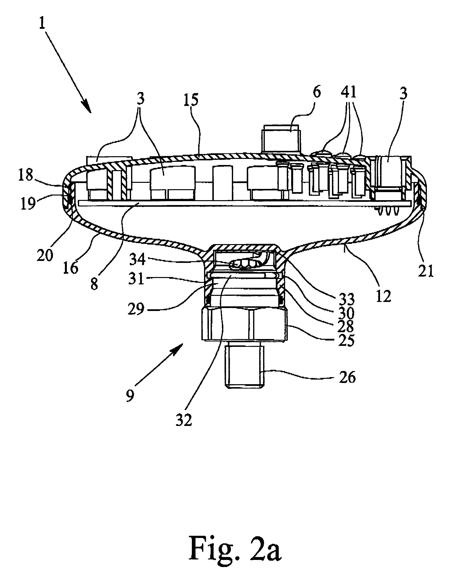
[0011]Making at least one mounting foot, first of all, results in the housing being spaced apart from the support surface, by which cleaning of the area between the housing bottom and the support surface is enabled. Here, it is such that, on the one hand, the possibility of cleaning becomes better, the farther the housing is spaced away from the support surface, and on the other hand, generally, only a limited installation space is available so that both for reasons of space and also for reasons of stability, the height of the electronic module cannot be increased arbitrarily. These two contradictory requirements are especially easily met in the electronic module of the invention in that the housing bottom has an increasing distance from the support surface in a direction from the mounting foot to the edge area. In this way, in spite of the limited overall height of the electronic module good cleaning of the area between the housing and the support surface is possible.
[0021]According to another embodiment of the electronic module of the invention, the mounting foot is made as a punched and bent part, the mounting foot or the punched and bent part having two legs which are arranged at an angle of less than 90 degrees relative to one another. This mounting foot can be produced very easily, by placing the two legs at an angle of less than 90 degrees relative to one another, the result being that the top of the housing is tilted when the support surface is horizontal. In this way, on the one hand, the operator surface of the electronic module is inclined, by which its accessibility is facilitated, and on the other hand, the result is that spray water automatically flows off when the housing is cleaned so that “puddling” on the top of the housing is prevented. The mounting foot can be attached to the housing, especially to the housing bottom part, by welding, especially by resistance welding.

Problems solved by technology

Here, it is such that, on the one hand, the possibility of cleaning becomes better, the farther the housing is spaced away from the support surface, and on the other hand, generally, only a limited installation space is available so that both for reasons of space and also for reasons of stability, the height of the electronic module cannot be increased arbitrarily.

Method used


Image

  • Electronic module
  • Electronic module
  • Electronic module

Examples


Embodiment Construction

[0030]FIG. 1 shows a first preferred embodiment of an electronic module 1 that has a housing 2, with a total of eight jacks for connection of the electrical lines 4 shown in FIG. 4 and with one jack 5 and one plug 6 for connection of a bus line 7 which is likewise shown only in FIG. 4. Using this electronic module 1, it is possible for a total of eight sensors or actuators, which are connected to the lines 4, to connect to the bus line 7. The electrical connection of the jacks 3 to the jack 5 or the plug 6 takes place via the electronic unit which is located within the housing 2 and which comprises a circuit board 8 which has been assembled accordingly. The assembly of the circuit board 8 depends especially on whether conventional sensors and actuators or “intelligent” sensors or actuators which internally have an electronic unit for matching signals to the bus line are to be connected to the electronic module 1.

[0031]In the embodiment of the electronic module 1 of the invention, as...


PUM


Abstract

An electronic module (1) for connection of sensors or actuators to a bus line, with an electronic unit, with several jacks (3) for connection of electrical lines (4), and with one jack (5) and one plug (6) for connection of two bus lines (7). The electronic module (1) is especially well suited for use in the hygiene or foodstuffs fields since there is at least one mounting foot (9) for mounting of the electronic module (1) on a support surface (10) and that the housing (2) is made such that the edge area (14) of the housing bottom (12) is further from the support surface (10) than is the area of the housing by the mounting foot (9).

Description

BACKGROUND OF THE INVENTION[0001]1. Field of the Invention[0002]The invention relates to an electronic module for connection of sensors or actuators to a bus line, with a housing, with an electronic unit, with at least one jack or a plug for connection of electrical, optical, pneumatic or hydraulic lines, with at least one jack or one plug for connection of at least one bus line.[0003]2. Description of Related Art[0004]These electronic modules are used to connect several sensors or actuators to a bus line via which sensors and actuators are connected both to power and also to a central control. The bus line is generally an unshielded two-lead ribbon cable or standard round cable via which signals and power are transmitted at the same time. The electronic module is generally comprised of a circuit board which is assembled according to requirements and which is kept in a housing. If the jack and / or the plug is used for connection of pneumatic or hydraulic lines, pneumatic valves and / o...

Claims


Application Information

Patent Timeline
IPC IPC(8): H05K5/00H01R9/26H01R31/00H05K7/14
CPCH01R9/2658H05K7/1472H01R31/005
Inventor ROEHM, THOMASSTRAUSS, MICHAELWIENZEK, PETER
Owner IMF ELECTRONIC GMBH
Learn More