
Reduction of copper dewetting by transition metal deposition

a transition metal and copper technology, applied in the direction of solid-state devices, molten spray coatings, coatings, etc., can solve the problems of increasing reducing the probability of errors, and reducing the likelihood of errors, so as to achieve the effect of minimizing dewetting

Inactive Publication Date: 2007-09-04
APPLIED MATERIALS INC
View PDF89 Cites 46 Cited by
  • Summary
  • Abstract
  • Description
  • Claims
  • Application Information

AI Technical Summary

Benefits of technology

The present invention provides a method and apparatus for depositing layers on a substrate with a transition metal layer to minimize dewetting while maintaining the desired crystalline structure of the metal. This can be useful in the formation of electronic devices and other structures where the deposition of metal layers is important. The invention also includes methods for depositing layers on a substrate with a via to reveal metal at the base of the via, and for depositing layers on a bulk metal layer with a transition metal layer and optionally a capping layer. Overall, the invention provides a way to deposit metal layers on a substrate with improved quality and efficiency.

Problems solved by technology

Filling the features without creating voids or deforming the feature geometry is more difficult when the features have higher aspect ratios.
Reliable formation of interconnects is also more difficult as manufacturers strive to increase circuit density and quality.
Each processing method may increase the likelihood of errors such as copper diffusion across boundary regions, copper crystalline structure deformation, and dewetting.
These options are costly or only partially effective or both.
The stress migration and electromigration of copper across the dielectric layers or other structures increases the resistitivity of the resulting structures and reduces the reliability of the resulting devices.

Method used


Image

  • Reduction of copper dewetting by transition metal deposition
  • Reduction of copper dewetting by transition metal deposition
  • Reduction of copper dewetting by transition metal deposition

Examples


Embodiment Construction

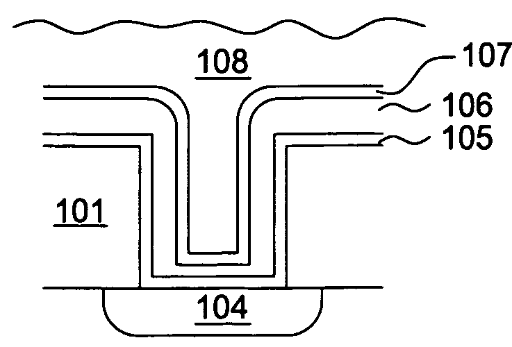
[0021]The present invention uses a transition metal to prevent copper dewetting and to stabilize copper crystalline structure in interconnect boundary regions. The transition metal, for example, ruthenium, improves copper boundary region properties to promote adhesion, decrease diffusion and agglomeration, and encourage uniform roughness and wetting of the substrate surface during processing. Deposition of ruthenium to improve the dewetting of a copper seed layer before bulk fill copper deposition is presented. Deposition of ruthenium to help preserve the copper crystallinity in the base of a via is also presented. Deposition of ruthenium after copper has been deposited to fill a via before an optional additional capping layer is deposited is presented.

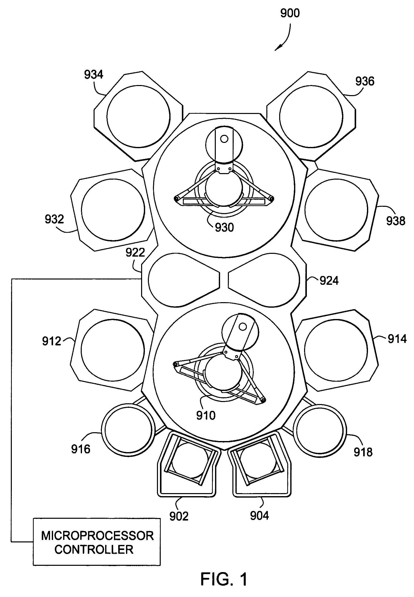
[0022]FIG. 1 is a schematic top-view diagram of an exemplary multi-chamber processing system 900. A similar multi-chamber processing system is disclosed in commonly assigned U.S. Pat. No. 5,186,718, entitled “Staged Vacuum Wafer Proce...


PUM

PropertyMeasurementUnit
temperatureaaaaaaaaaa
diameteraaaaaaaaaa
diameteraaaaaaaaaa

Abstract

A method and apparatus for forming layers on a substrate comprising depositing a metal seed layer on a substrate surface having apertures, depositing a transition metal layer over the copper seed layer, and depositing a bulk metal layer over the transition metal layer. Also a method and apparatus for forming a via through a dielectric to reveal metal at the base of the via, depositing a transition metal layer, and depositing a first metal layer on the transition metal layer. Additionally, a method and apparatus for depositing a transition metal layer on an exposed metal surface, and depositing a layer thereover selected from the group consisting of a capping layer and a low dielectric constant layer.

Description

BACKGROUND OF THE INVENTION[0001]1. Field of the Invention[0002]The present invention generally relates to a metallization process for manufacturing semiconductor devices. More particularly, the present invention relates to preventing copper dewetting by depositing a transition metal that helps preserve the copper crystal structure and promote adhesion between copper and other materials.[0003]2. Description of the Related Art[0004]Copper is the current metal of choice for use in multilevel metallization processes that are crucial to semiconductor device manufacturing. The multilevel interconnects that drive the manufacturing processes require planarization of high aspect ratio apertures including contacts, vias, lines, and other features. Filling the features without creating voids or deforming the feature geometry is more difficult when the features have higher aspect ratios. Reliable formation of interconnects is also more difficult as manufacturers strive to increase circuit dens...

Claims


Application Information

Patent Timeline
Patent Type & Authority Patents(United States)
IPC IPC(8): H01L21/4763
CPCH01L21/28556H01L21/76846H01L21/76868H01L21/76873H01L2221/1089H01L21/76843H01L21/76849
Inventor CHUNG, HUAGANGULI, SESHADRIMARCADAL, CHRISTOPHEYU, JICK M.
Owner APPLIED MATERIALS INC
Learn More