
Control device of hybrid drive unit

a control device and hybrid drive technology, applied in the direction of electric devices, propulsion parts, propulsion using engine-driven generators, etc., can solve the problems of affecting the performance of the torque to appear on the output shaft at the shifting time may be different from the expected, and the control has a tendency to elongate the time period necessary for the gear shift, etc., to achieve the effect of eliminating shocks

Active Publication Date: 2007-08-28
TOYOTA JIDOSHA KK
View PDF54 Cites 20 Cited by
  • Summary
  • Abstract
  • Description
  • Claims
  • Application Information

AI Technical Summary

Benefits of technology

[0017]An object of this invention is to provide a control device for a hybrid drive unit, which can eliminate shocks, as might otherwise be caused by a gear shift in a transmission having an output member connected to an assist prime mover.
[0018]Another object of this invention is to provide a control device, which can suppress or prevent such fluctuation or fall of the torque of the output member, as might otherwise accompany the gear shift in the transmission having the output member connected to an electric motor.
[0019]Still another object of this invention is to provide a control device, which can suppress or prevent the shocks by controlling the transmission to accurately grasp the relation between a torque capacity and an apply pressure of a frictional engagement devise.

Problems solved by technology

The aforementioned device has such advantages, but shocks may occur in case the gear shifting operation is done by the transmission.
As a result, the entire output torque of the hybrid drive unit or the drive torque of the vehicle may change during the gear shift thereby to cause the shocks.
This control has a tendency to elongate the time period necessary for the gear shift.
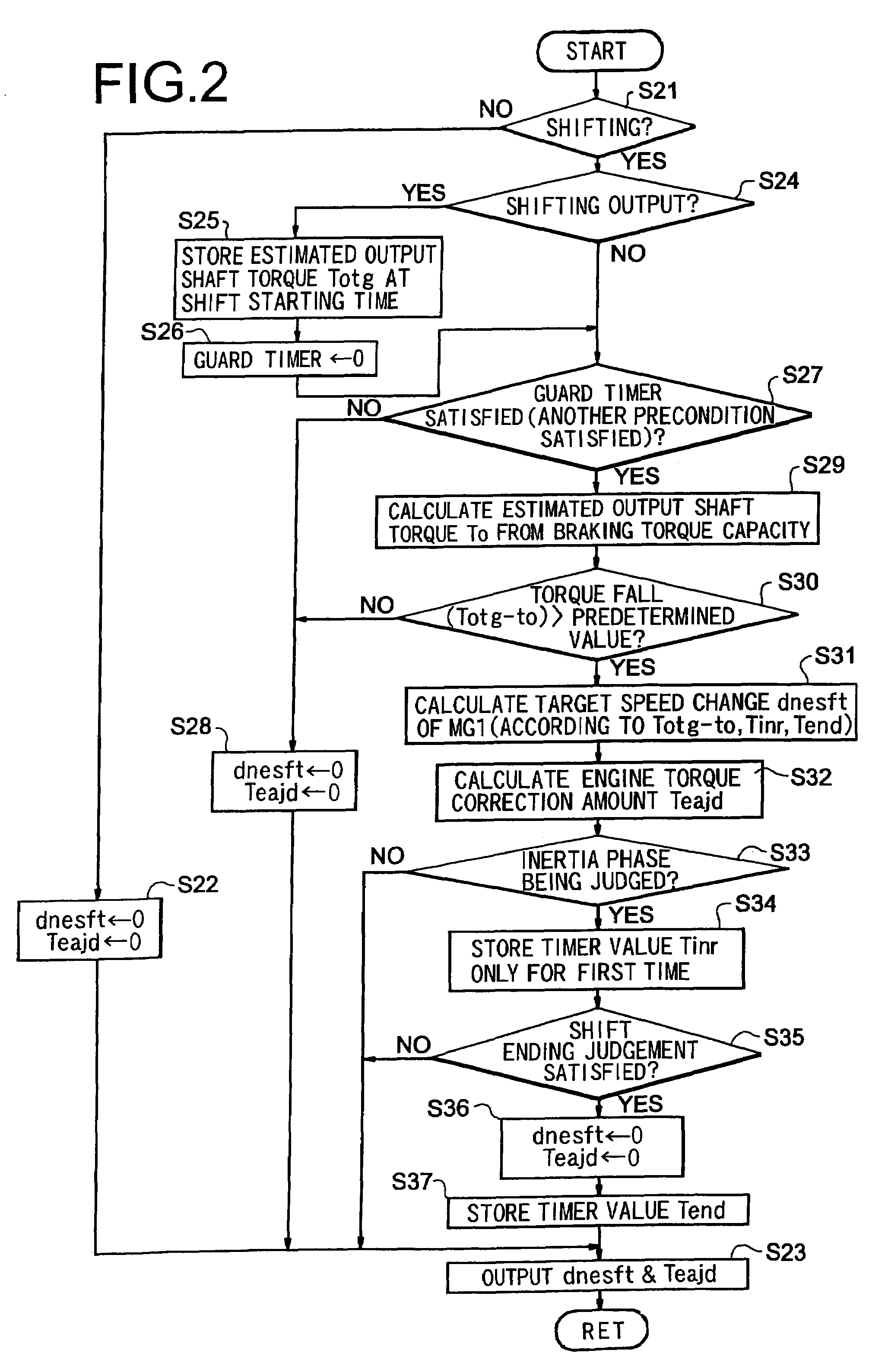
However, the relation between the apply pressure and the torque capacity of the frictional engagement device such as the clutch or the brake is not constant due to the individual difference or the aging so that the torque to appear on the output shaft at the shifting time may become different from the expected one to deteriorate the shocks.
As a result, the output shaft torque may become short or excessive to cause the shocks.
Therefore, it is possible to learn the initial apply pressure for optimizing the change in the speed at the shifting time, but it is impossible to precisely determine the relation between the torque capacity and the apply pressure of the frictional engagement device to participate in the gear shift.

Method used


Image

  • Control device of hybrid drive unit
  • Control device of hybrid drive unit
  • Control device of hybrid drive unit

Examples


Embodiment Construction

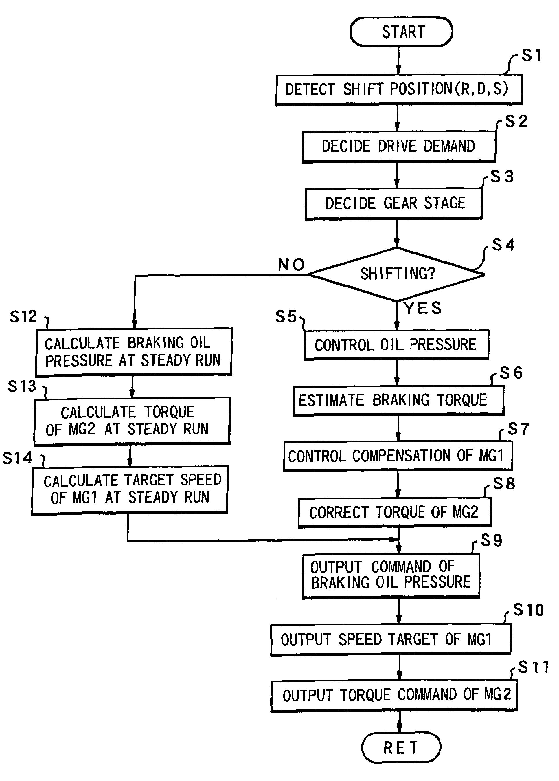
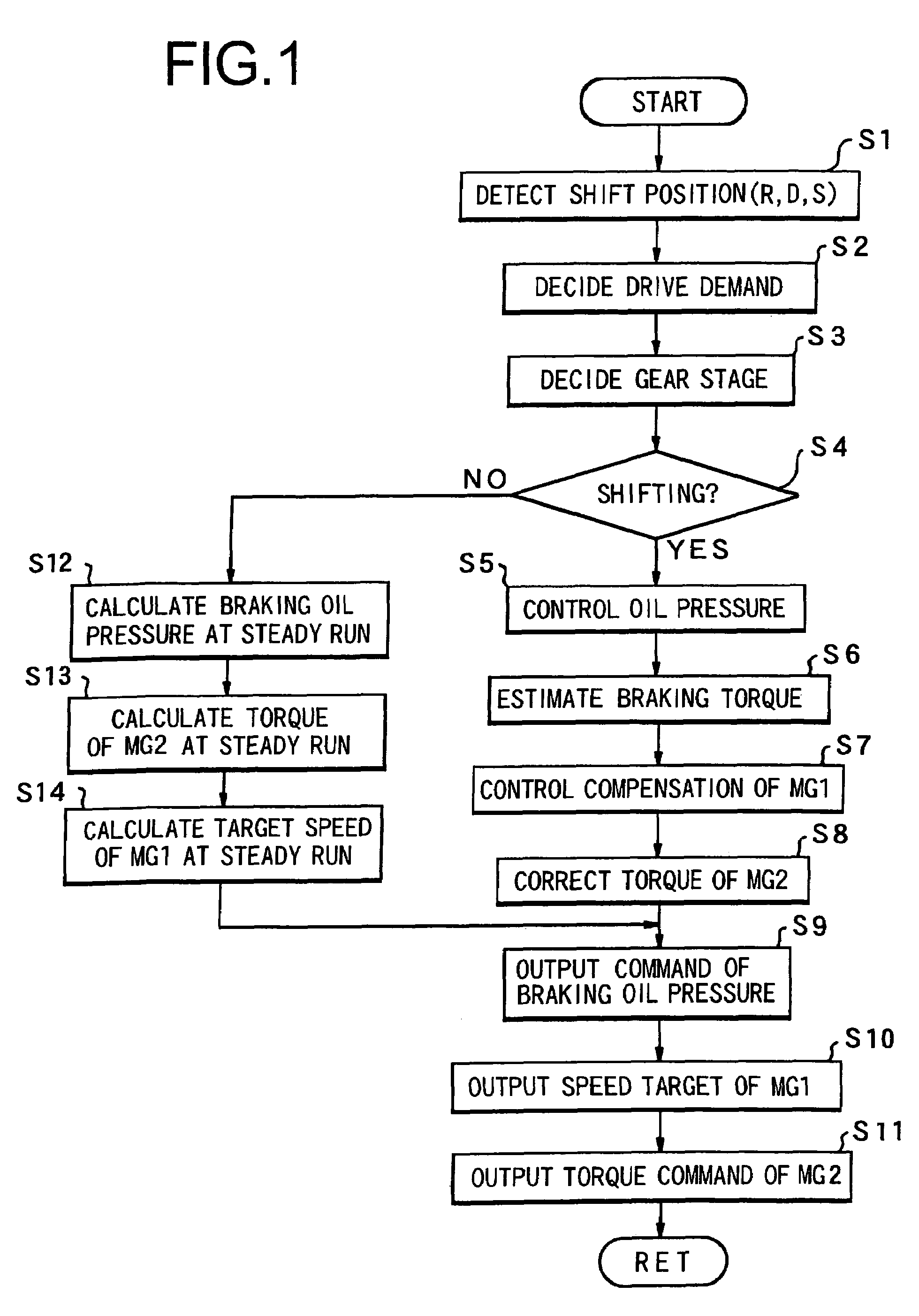
[0069]This invention will be described in connection with its specific examples. The first description is made on a hybrid drive unit, to which is this invention is applied. The hybrid drive unit or an application target of this invention is mounted on a vehicle, for example. As shown in FIG. 15, the torque of a main prime mover 1 is transmitted to an output member 2, from which the torque is transmitted through a differential 3 to drive wheels 4. On the other hand, there is provided an assist prime mover 5, which can make a power control to output a driving force for a drive and a regenerative control to recover energy. This assist prime mover 5 is connected through a transmission 6 to the output member 2. Between the assist prime mover 5 and the output member 2, therefore, the transmission torque capacity is increased / decreased according to a gear ratio to be set by the transmission 6.

[0070]This transmission 6 can be constructed to set the gear ratio at “1” or higher. With this co...


PUM


Abstract

A control device of a hybrid drive unit, wherein an assist prime mover is connected through a transmission to an output member, to which a torque outputted by a main prime mover is transmitted. The control device comprises a first torque correcting means for correcting the torque to be transmitted from the main prime mover to the output member during a gear shift by the transmission.

Description

CROSS REFERENCE TO RELATED APPLICATIONS[0001]This application is a continuation under 35 U.S.C. §120 of application Ser. No. PCT / JP03 / 16046, filed Dec. 25, 2003 and is also based upon and claims priority under 35 U.S.C. §119 from Japanese Patent Application Nos. 2002-374973, filed Dec. 25, 2002, 2002-374975, filed Dec. 25, 2002, and 2002-374978, filed Dec. 25, 2002, the entire contents of each of which are incorporated herein by reference.FIELD OF THE INVENTION[0002]This invention relates to a hybrid drive unit provided with two kinds of prime movers as a power source for driving a vehicle, and more particularly, to a control device for a hybrid drive unit, wherein an assist prime mover is connected through a transmission to an output member, to which a torque is transmitted from a main prime mover.BACKGROUND OF THE INVENTION[0003]In a vehicular hybrid drive unit, an internal combustion engine such as a gasoline engine or a Diesel engine and an electric device such as a motor genera...

Claims


Application Information

Patent Timeline
Patent Type & Authority Patents(United States)
IPC IPC(8): B60K1/02B60K6/365B60W20/00B60K6/445B60K6/48B60K6/485B60K6/547B60L50/16B60W10/04B60W10/06B60W10/08B60W10/10B60W10/11F16H3/72F16H59/40F16H59/42F16H61/04F16H61/16F16H61/686F16H63/12F16H63/50
CPCB60K6/445B60K6/48B60W10/02B60W10/08B60W10/10F16H3/728F16H61/0437B60L3/12B60L7/14B60L11/123B60L11/14B60L15/2009B60K6/365B60K1/02Y10T477/23B60L2240/423B60W20/00B60W2710/0666B60W2710/083F16H61/686F16H2037/0873F16H2061/0433F16H2200/2007Y02T10/6221Y02T10/6239Y02T10/642Y02T10/7258B60L2210/40B60L2240/421B60L2240/441B60L2240/443B60L2240/486B60L2240/80B60L2250/24B60L2260/42B60L2260/44B60L2270/145Y10T477/26B60L50/61B60L50/16Y02T10/62Y02T10/64Y02T10/72Y02T10/7072Y02T10/70B60W2710/027B60W2510/0657
Inventor ENDO, HIROATSUOZEKI, TATSUYASUGIYAMA, MASATAKA
Owner TOYOTA JIDOSHA KK
Learn More