Eureka AIR delivers breakthrough ideas for toughest innovation challenges, trusted by R&D personnel around the world.

Power assisted bicycle

a technology of power assisted bicycles and bicycles, which is applied in the direction of vehicle components, rider propulsion, vehicle components, etc., can solve the problems of motor operation and compels the rider to pedal, and achieve the effects of reducing the overall performance of the bicycle, and reducing the fatigue of the rider

Inactive Publication Date: 2007-08-28
FAHRNER TODD
View PDF9 Cites 29 Cited by
  • Summary
  • Abstract
  • Description
  • Claims
  • Application Information

AI Technical Summary

Benefits of technology

[0018]Power-assisted bicycles have typically provided reluctant or unfit bicyclists relief from hard work in transporting only themselves. The present invention is offered as a means of enabling fit bicyclists to accomplish work normally relegated to much heavier vehicles, such as transporting heavy cargo or passengers in hilly terrain, with trip times comparable to those of automobiles in urban environments. Because it is uncomfortable and wasteful of motor power to let one's legs be forcibly driven by the cranks, motor-driven cranks solicit a significant power contribution from the rider, thus elevating the bicycle's overall performance and the rider's physical condition. Furthermore, a fixed-ratio coupling of the motor's rotation to that of the rider's legs assures that the motor's power and efficiency will be maintained at desirable levels as the bicyclist shifts gears to regulate his or her own pedaling cadence.

Problems solved by technology

Operation of the motor, however, compels the rider to pedal.
Because it is uncomfortable and wasteful of motor power to let one's legs be forcibly driven by the cranks, motor-driven cranks solicit a significant power contribution from the rider, thus elevating the bicycle's overall performance and the rider's physical condition.

Method used


Image

  • Power assisted bicycle
  • Power assisted bicycle
  • Power assisted bicycle

Examples


Embodiment Construction

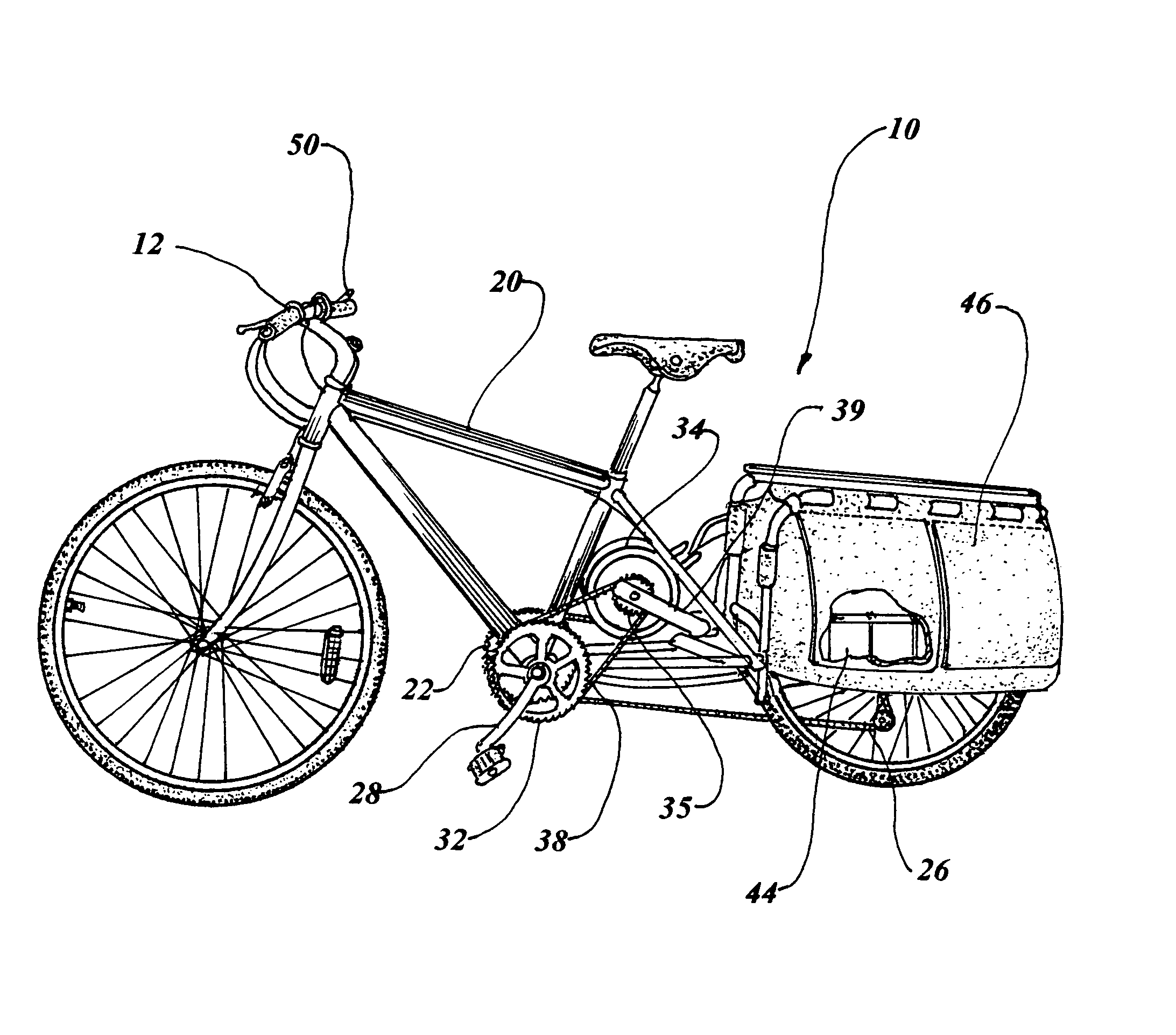
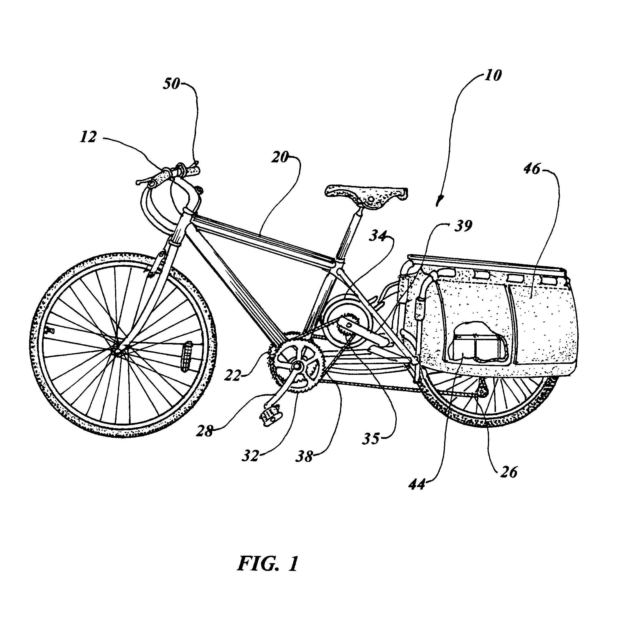
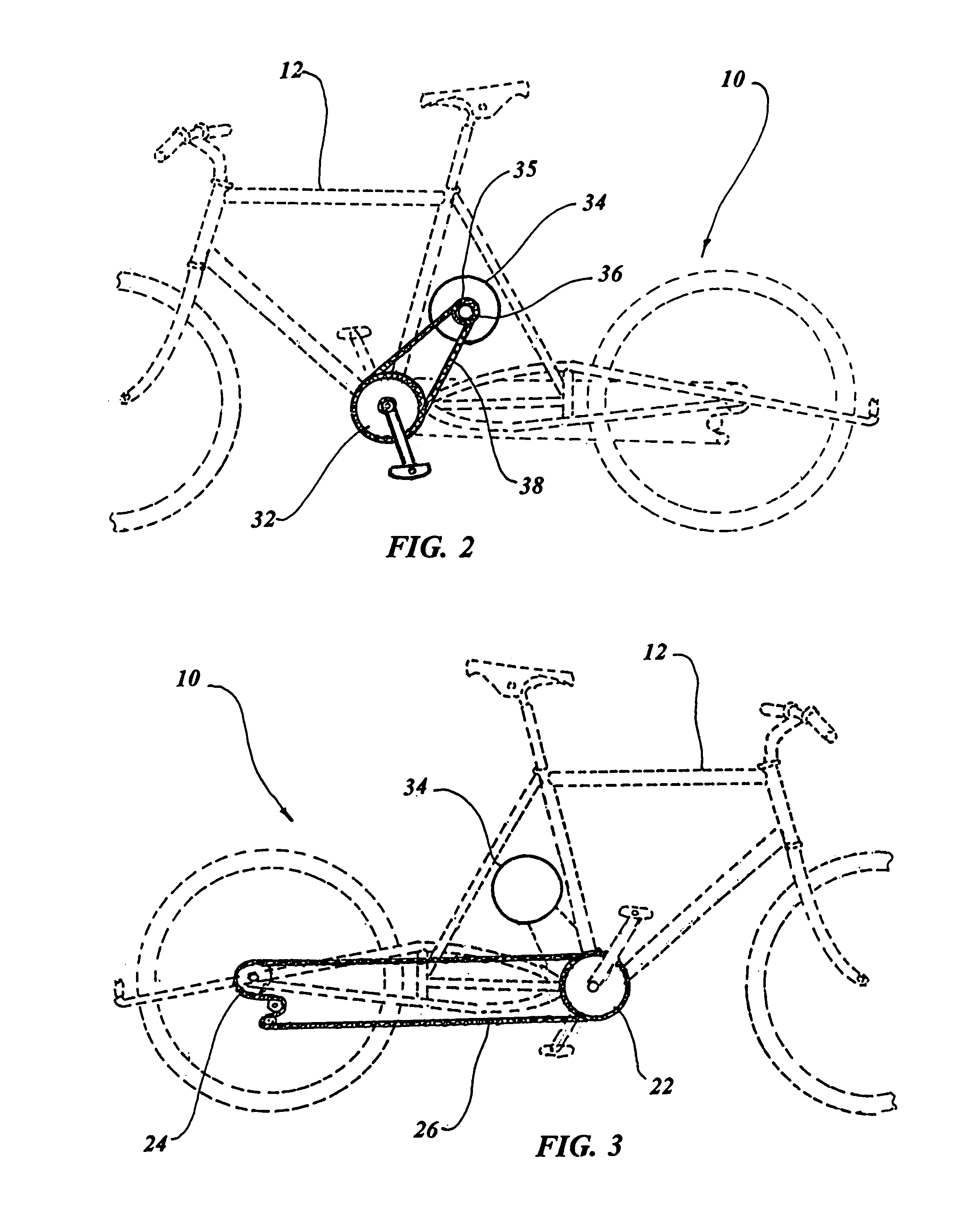
[0027]The best mode for carrying out the invention is presented in terms of a preferred embodiment for a power assisted bicycle 10. The preferred embodiment, as shown in FIGS. 1 through 7, is comprised of a manually powered bicycle 12 having a frame 20, a bicycle drive sprocket 22, a bicycle driven sprocket 24, a bicycle roller chain ring 26 that connects the bicycle drive sprocket 22 to the bicycle driven sprocket 24, and the bicycle 12 having a pair of pedal crank arms 28 manually rotating the bicycle drive sprocket 22. This bicycle drive sprocket 22 consists of at least one sprocket, and the bicycle driven sprocket 24 may also be a single sprocket or a plurality of sprockets, according to the type of bicycle that is utilized as a component of the invention.

[0028]The invention is versatile enough to be incorporated into a wide variety of manually operated vehicles, such as a conventional diamond frame bicycle, an elongated wheelbase bicycle, a tandem bicycle (less second “stoker” ...


PUM


Abstract

A power assisted bicycle (10) which modifies an existing manually powered bicycle (12) by replacing the left pedal crank arm with a motor-driven sprocket and left pedal assembly (32). An electric motor (34) is attached to the bicycle's frame (20) and has attached a motor drive sprocket (35) and a one-way clutch (36). A motor roller chain ring (38) is connected in concert to the motor drive sprocket (35) and motor driven sprocket (32), such that the electric motor (34), provides a power assist to the manually powered bicycle, with the one-way clutch (36) permitting unassisted pedaling without resistance of the motor when de-energized. An electrical power source (40) interfaces with an electrical control system (42) for supplying electrical energy to operate and control the electric motor.

Description

CROSS REFERENCE TO RELATED APPLICATION[0001]This application claims priority of Provisional Patent Application Ser. No. 60 / 612,430 filed Sep. 24, 2004.TECHNICAL FIELD[0002]The invention generally pertains to the field of pedaled crank vehicles and more particularly to a bicycle having a motor driven apparatus that drives the pedaled cranks and chainrings of the bicycle.BACKGROUND ART[0003]Prior art patents include methods to permit a motor to transmit power to a bicycle wheel without intermediately driving the bicycle's pedal cranks, or to control a bicycle motor's output semi-automatically. These designs frequently entail mounting a motor in a location where it is likely to upset handling or limit ground clearance. The motor can also interfere with the rider's legs, the pedals as normally spaced, the front wheel, or the normal routing of the bicycle's control cables.[0004]The prior art listed below did not disclose patents that possess any of the novelty of the instant invention, h...

Claims


Application Information

Patent Timeline
Patent Type & Authority Patents(United States)
IPC IPC(8): B62K17/00
CPCB62M6/55
Inventor FAHRNER, TODD
Owner FAHRNER TODD
Why Eureka
Eureka Blog
Learn More