
Shared receive path for simultaneous received signals

a shared receive path and signal technology, applied in telephonic communication, substation equipment, electrical equipment, etc., can solve the problems of difficult for a single device to operate in more than one communication system, and inability of wireless devices to remain in the first operating mod

Inactive Publication Date: 2007-08-21
QUALCOMM INC
View PDF7 Cites 171 Cited by
  • Summary
  • Abstract
  • Description
  • Claims
  • Application Information

AI Technical Summary

Problems solved by technology

Within a particular type of wireless communication device there may be a number of different specifications that make it difficult for a single device to operate in more than one communication system.
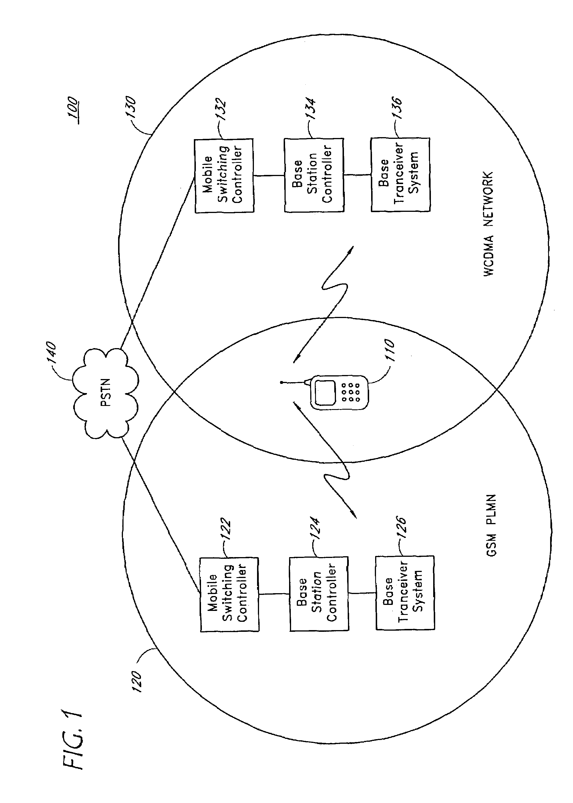
When signal quality for a communication link using the first mode may degrades to an unacceptable quality of service, the wireless device can attempt to hand off the communication link from a base station in a first cell to a base station in a second cell.
Thus it may not be possible for the wireless device to remain in the first operating mode.
Unfortunately, the first and second operating modes may use communication channels in different frequency bands and may also use incompatible modulation techniques.
The wireless phone may attempt to hand off the communication link to another GSM base station, but there may not be any other GSM base station that can provide a communication link having an improved quality of service.
However, operating in the compressed mode is highly complex.
The timing issues that must be controlled in the compressed operating mode make it difficult to implement a wireless phone using compressed mode.
The additional parts needed for the two receiver implementation also increase the total cost of manufacturing the wireless phone.

Method used


Image

  • Shared receive path for simultaneous received signals
  • Shared receive path for simultaneous received signals
  • Shared receive path for simultaneous received signals

Examples


Embodiment Construction

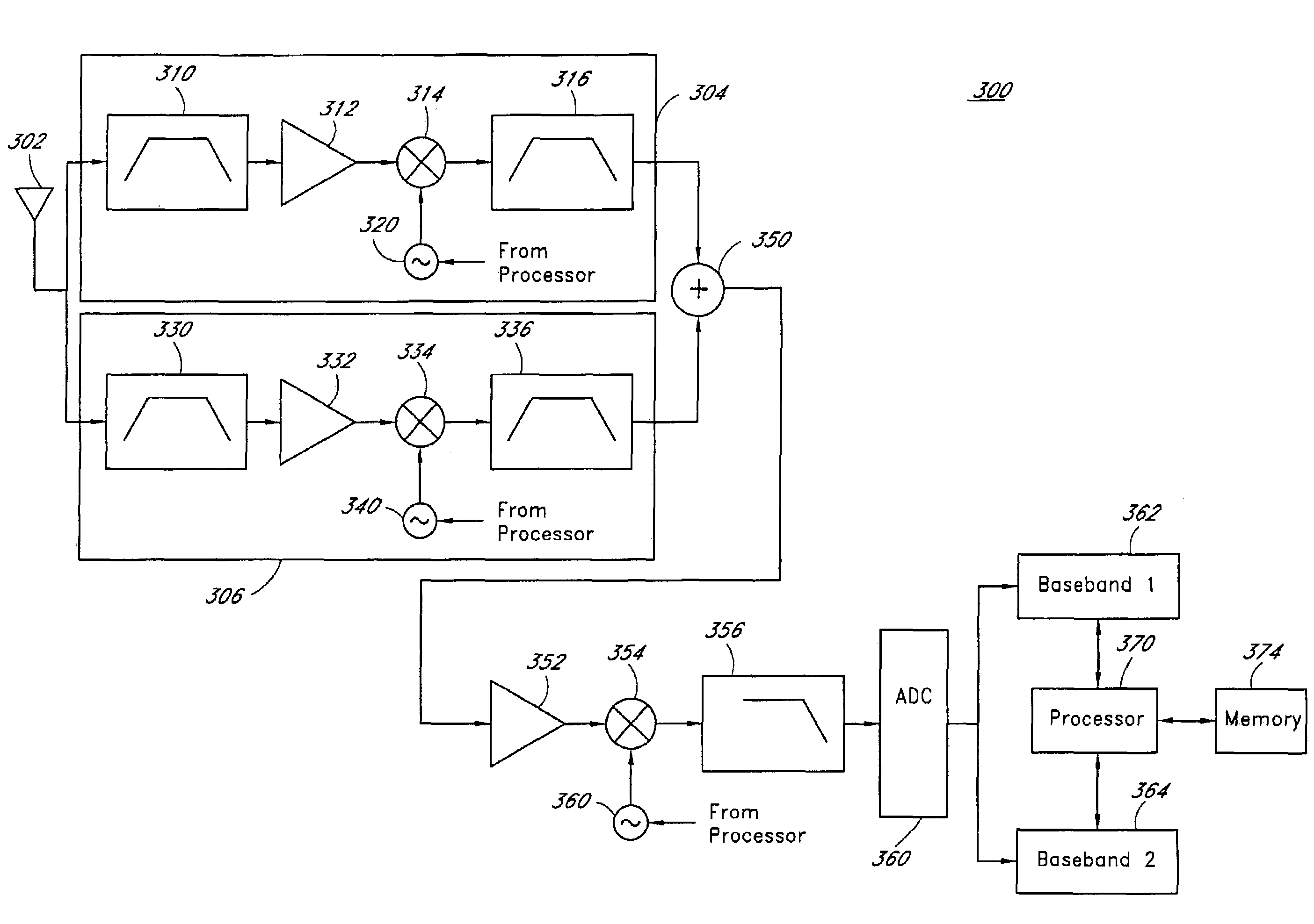
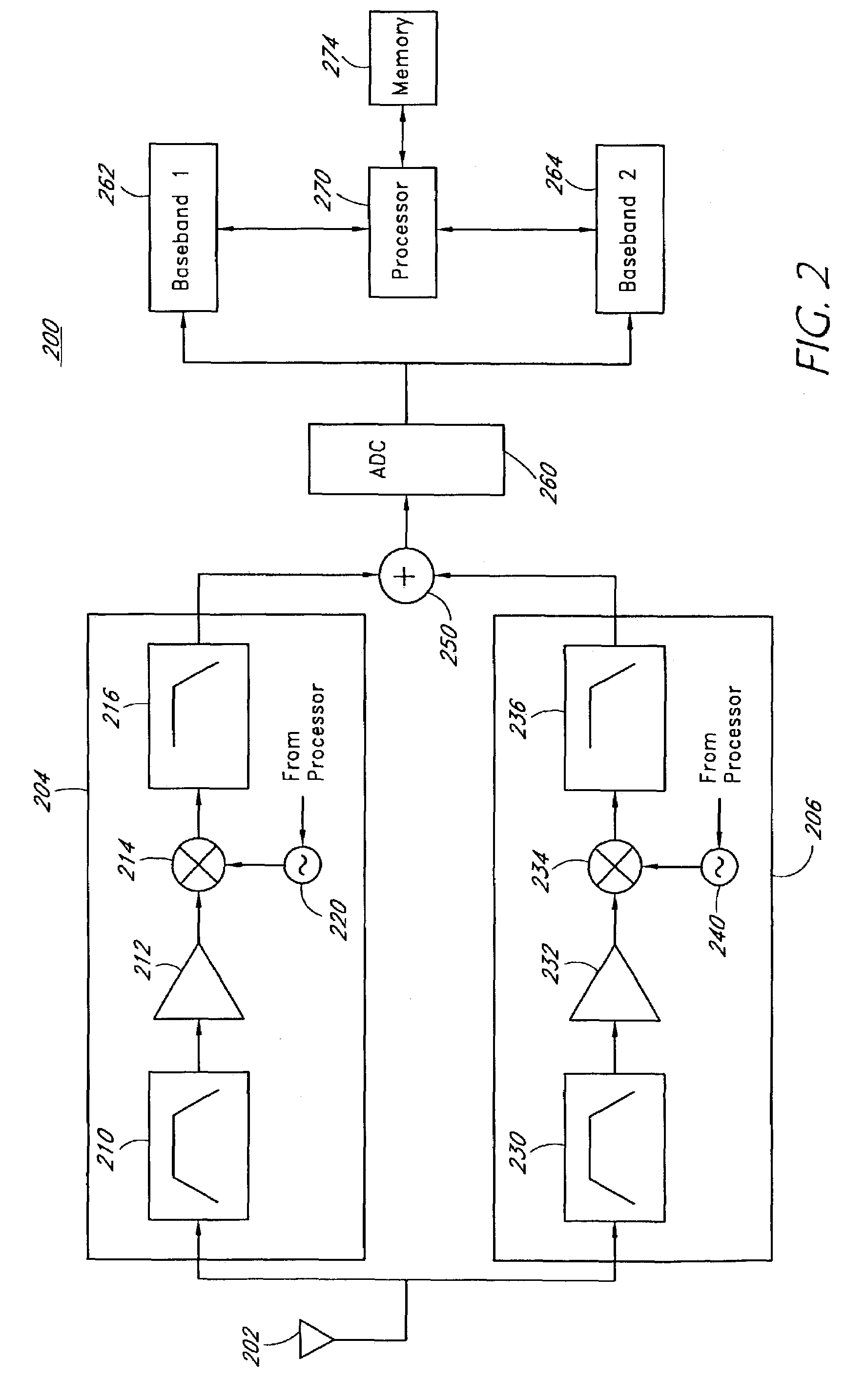
[0022]A method and apparatus configured to simultaneously receive multiple signals using a shared receive path are disclosed. Using the method or apparatus, a WCDMA signal may be received and converted to a WCDMA baseband signal. Simultaneously, a GSM signal may be received and converted to a GSM baseband signal. At least a portion of the bandwidth occupied by the WCDMA baseband signal overlaps a portion of the bandwidth occupied by the GSM baseband signal. The two baseband signals are then combined into a combined baseband signal. A first baseband processor operates on the combined signal to extract information from the WCDMA signal component of the combined signal. Similarly, a second baseband processor operates on the combined signal to extract information from the GSM signal component of the combined signal. Accordingly, devices implementing the apparatus can simultaneously receive both GSM and WCDMA signals and therefore easily handoff between base stations operating in differe...


PUM


Abstract

A method and apparatus are disclosed for a wireless communication device to simultaneously receive at least two signals. Two receiver portions are provided in the wireless communication device. A first receiver portion is configured to receive a first communication signal. A second receiver portion is configured to receive a second communication signal. The two receiver portions are configured to convert the first and second communication signals to a common frequency band. The common frequency band may be an intermediate frequency band or baseband frequency band. The converted first and second communication signals are combined in the common frequency band using an adder or other signal combiner. The combined signal is processed in a single signal processor. The communication device is able to resolve each of the received signals when the first communication signal is a narrowband signal and the second communication signal is a wideband signal, such as a spread spectrum signal.

Description

BACKGROUND OF THE INVENTION[0001]1. Field of the Invention[0002]The invention relates to wireless communication devices. More particularly, the invention relates to receivers in multimode wireless communication devices.[0003]2. Description of the Related Art[0004]A vast array of wireless communication devices is available for consumer use. The communication devices include pagers, two-way radios, and wireless phones, such as cordless phones, cellular phones, and personal communications service (PCS) phones.[0005]The multiple wireless devices typically operate in different frequency bands and different communication systems that operate according to detailed specifications. Within a particular type of wireless communication device there may be a number of different specifications that make it difficult for a single device to operate in more than one communication system. For example, in the field of wireless phones there are numerous specifications and standards.[0006]Wireless phone ...

Claims


Application Information

Patent Timeline
Patent Type & Authority Patents(United States)
IPC IPC(8): H04M1/00H04B1/40H04W88/06
CPCH04B1/406H04W88/06
Inventor SHIPPEE, GEOFFREY
Owner QUALCOMM INC
Learn More